


Tianjin SWKS Technology & Development Co.,Ltd is one of the most reliable manufacturers and suppliers of custom pom industrial linear actuator anti-rotation block in China. If you're going to buy bulk cheap custom pom industrial linear actuator anti-rotation block, welcome to get quotation from our factory. Quality products and low price are available.
Custom POM Industrial Linear Actuator Anti-Rotation Block
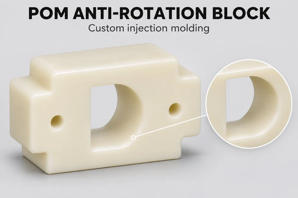
SWKS offers custom POM anti-rotation blocks for linear actuator assemblies and guided positioning mechanisms. A shaped internal profile works with a matching member to control its angular orientation while allowing the movement specified by the equipment designer. Mounting features, guide length and profile clearance are manufactured to the approved drawing. Send your model and order quantity to amanda@tjswks.com for a project review. The pictured component is an example of a custom acetal block rather than a universal actuator replacement.
Keeping A Translating Member In Its Intended Orientation
In a linear mechanism, translation and rotation are separate movements. Some actuator arrangements need the output member to travel axially while its orientation remains controlled. An anti-rotation block provides a geometric interface for that purpose. A noncircular opening engages a corresponding profile, and the relationship between the contact surfaces determines the available angular movement. The exact arrangement depends on the surrounding mechanism.
The illustrated block uses a shaped opening and external mounting features. Its flat profile is intended to demonstrate how a custom molded guide can be adapted to a matching member. Before quotation, identify which part moves, which part is fixed and where the reaction is transferred to the equipment. This is necessary to understand the function of the molded component within the assembly.
An anti-rotation feature does not automatically carry every load in a linear system. Axial thrust, bending moments and guidance may be handled by other components. The equipment drawing should separate these functions and identify the loads that reach the block. We review the proposed geometry against those stated requirements without assigning a load rating from the appearance of the example.
Custom Block Specification
| Feature | Custom requirement |
|---|---|
| Product | Linear actuator anti-rotation block |
| Material | POM / acetal, grade subject to application review |
| Production | Custom injection molding |
| Internal profile | D-shaped or customer-defined noncircular guide opening |
| Mounting | Hole centers, shoulders and seating planes to drawing |
| Fit basis | Agreed mating profile, clearance and inspection conditions |
| Files | STP, STEP, IGS with dimensioned PDF |
| Approval | Drawing review and samples tested in the intended mechanism |
Defining The Mating Profile And Angular Clearance
The mating member is the starting point for the internal opening. Provide its cross section with the actual dimensional limits, corner radii and surface condition. A nominal diameter does not fully define a D-shaped guide. The distance to the flat, the transition at each corner and the profile orientation are all relevant to engagement. A section drawing makes these relationships clear.
Clearance should permit the intended sliding movement while meeting the assembly requirement for angular play. Reducing a clearance can change both fit and contact pressure. The equipment designer should specify the allowable movement at the functional interface. We can then review how that target relates to the molded dimensions and the practical inspection method for the block.
The guide profile should also account for the mating member throughout its travel. A local feature, joint or finish transition may pass through the opening during operation or assembly. Identify these features in the model. A block that fits one measured section of a shaft may behave differently if the shaft profile varies along its length.
Corner relationships deserve attention because they can prevent the broad faces from seating as intended. A small radius on the mating flat may require a corresponding relief in the opening. Conversely, excessive relief may reduce the available contact region. The approved cross section should define the functional faces and distinguish them from clearance areas that do not carry the intended reaction.
Guide Length, Contact Faces And Installation Alignment
The length of the internal engagement influences how the block contacts its mating member. A longer guide surface can distribute contact differently, but it also makes alignment important. If the block is tilted relative to the moving member, contact may concentrate at an edge. The mounting arrangement should establish the intended guide axis rather than relying on the fasteners to pull a misaligned block into position.
Specify the relationship between the internal profile and the seating plane. Hole position alone may not fully locate the guide axis. A shoulder, locating feature or separate fixture may establish the final position in the mechanism. The drawing should identify the datum scheme that represents this assembly relationship so that inspection addresses the dimensions that control actual fit.
When two guide locations are used, provide their spacing and alignment requirements together. Two individually acceptable blocks can still create resistance if the installation axes do not coincide as required. The equipment team should check the full travel with the intended assembly procedure. Any adjustment slots or locating references should be shown clearly in the project drawing.
Fastener access and service removal should be reviewed before tooling. A screw head, washer or adjacent rail may obstruct the moving member even when the block itself clears it. The external envelope needs to include these items. If the block is a replaceable wear element, identify the removal direction and the space needed to withdraw it from the mechanism.
Reviewing POM For The Sliding Interface
POM is used for many molded mechanical components because it can provide useful stiffness and sliding behavior. The performance of a particular guide still depends on the selected grade and contact conditions. Please provide the mating material, travel speed, stroke, operating cycle and expected environment. These inputs help distinguish a lightly loaded locating guide from a repeatedly loaded sliding interface.
Friction and wear are properties of the interacting system. The counterpart finish, contamination, lubrication and alignment can influence the result. A general statement about acetal should not be treated as a guaranteed service life for an unspecified mechanism. Where wear is an acceptance criterion, define the relevant operating trial and measurement method before the sample stage.
Temperature and exposure conditions also belong in the material review. Include cleaning agents, oils and any intermittent heat sources close to the guide. A special resin grade may be proposed when the requirements justify it, but material identification is confirmed within the offer. Color alone does not establish a particular formulation or performance level.
Related custom components can be found in our POM parts and plastic injection parts categories. Each project is evaluated according to its own geometry and application.
Mold Review For A Noncircular Through Opening
The tooling concept considers how the internal opening is formed and how the block releases from the mold. Draft, core support and parting direction must be reviewed alongside the required guide profile. A functional sliding face may need a different treatment from an external cosmetic wall. These requirements should be identified on the drawing before the tool design is finalized.
Wall transitions around the opening and mounting ears can influence molding behavior. Thick local sections may require a design discussion, particularly near a critical seating surface. We examine the model and propose changes where necessary for manufacture. No change to a functional dimension is treated as approved merely because it simplifies the mold arrangement.
Gate and ejection locations should be placed with the working surfaces in mind. The customer can identify areas where a normal molding witness is acceptable and areas where a controlled finish is required. This agreement is useful for both sample approval and repeat production. Clear visual criteria are more practical than an undefined expectation that all surfaces will look identical.

Inspection And Actuator Trial
Inspection can cover the shaped opening, mounting hole centers, block thickness, shoulder position and seating relationship. The chosen measurement method should reflect the function of the feature. A profile gauge or a controlled mating sample may supplement dimensional measurements when appropriate. Any gauge used as an acceptance reference should be identified and agreed so that future checks use the same basis.
Samples should be installed using the intended fasteners and locating arrangement. Check movement over the full stroke, including the approach to each end position. Record the conditions used for the trial, such as the mating member, lubrication and applied load. This provides useful evidence when deciding whether the profile clearance and mounting relationship are suitable for production.
If the trial identifies binding or excessive play, describe where it occurs and how it was measured. A drawing revision should identify the dimension or relationship being changed. Updating the model and inspection reference together prevents an adjustment from being lost between sample rounds. Production is released against the approved revision and the agreed acceptance criteria.
Quotation And Repeat Supply
Please send the part model, dimensioned drawing, mating profile and required quantity. Include estimated annual demand and any special packing or traceability requirements. If the starting point is a worn sample, distinguish the intended dimensions from the worn surfaces. Assembly photographs can help explain the function, but the final production definition should be captured in the approved drawing.
The quotation will state the tooling scope, proposed POM grade, part price, sample arrangements and estimated schedule. Inspection reports, fixtures and additional testing are included when agreed. For repeat orders, use the approved part number and revision to keep the guide configuration clear. Welcome to contact amanda@tjswks.com / 0086-15222707659 with your custom linear actuator anti-rotation block inquiry.
Hot Tags: custom pom industrial linear actuator anti-rotation block, China, suppliers, manufacturers, factory, bulk, cheap, low price, quotation, complex plastic injection parts, Custom Cast Urethane Polyurethane Parts, Low Quantity Injection Molding, packaging plastic injection parts, plastic parts for automotive industry, PP plastic part


