




Tianjin SWKS Technology & Development Co.,Ltd is one of the most reliable manufacturers and suppliers of pbt industrial terminal block partition plate in China. If you're going to buy bulk cheap pbt industrial terminal block partition plate, welcome to get quotation from our factory. Quality products and low price are available.
Custom PBT Partition Plates for Industrial Terminal Block Assemblies
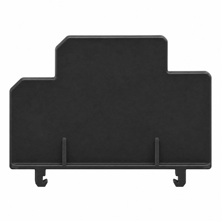
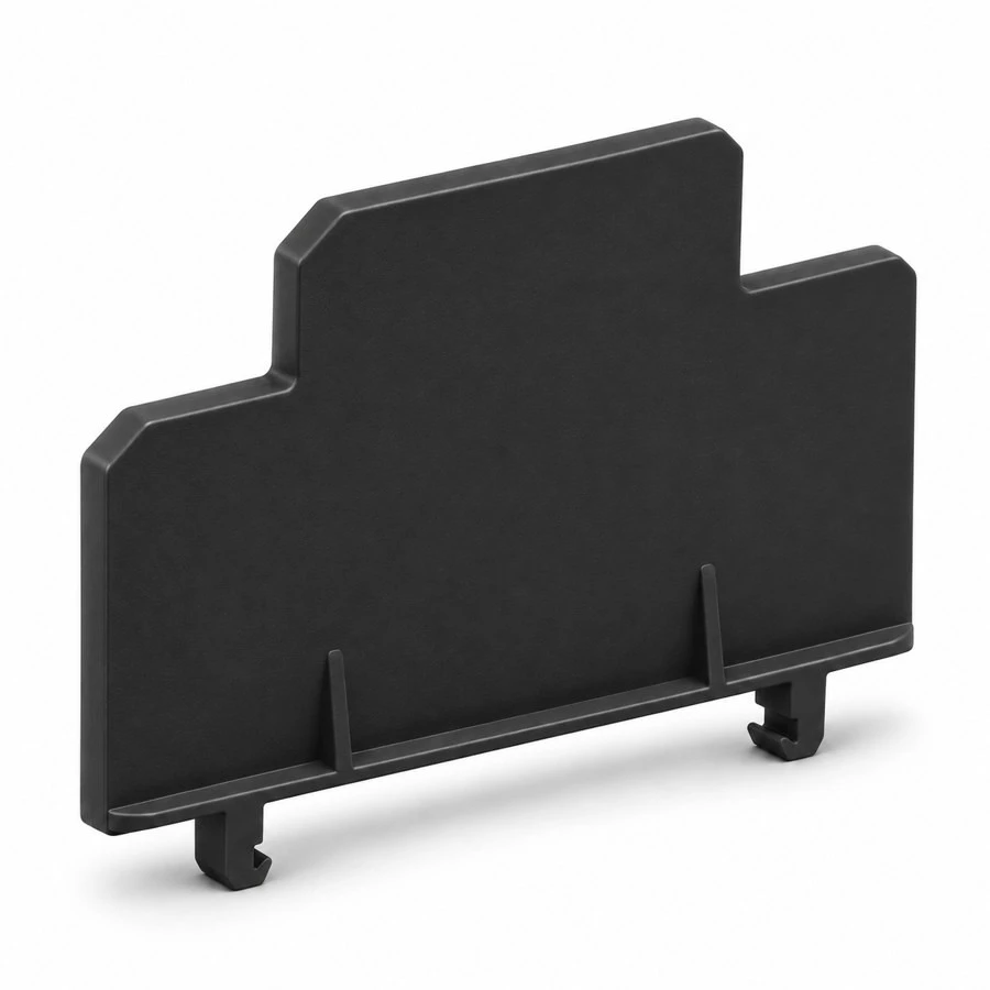
A terminal block partition plate creates a defined physical division between adjacent sections of a terminal assembly. Its outline follows the terminal profile, while its retaining features keep it located on the intended mounting arrangement. SWKS offers custom injection molding for PBT partition plates developed from approved customer drawings. The illustrated stepped divider with bottom retaining feet is a representative design concept. Send the terminal interface, drawing and order quantities to amanda@tjswks.com for a manufacturing review.
This component is different from a broad motor terminal barrier fixed to a machine base. A terminal block divider normally needs to fit a particular terminal family and mounting space, with a thin profile and carefully positioned retaining features. Compatibility cannot be established from overall height and width alone. Provide the mating terminal geometry, mounting rail details and installation sequence when requesting a custom design.
Determine the Separation Function
The first design question is what the divider must separate. It may distinguish circuit groups, provide a physical barrier between adjacent terminals or support a defined assembly layout. The equipment designer should specify the required function and the dimensions that achieve it. A molded divider by itself does not establish the electrical rating of the complete terminal system, and an arbitrary increase in plate height is not a substitute for a system-level design review.
Identify the accessible wiring and tool paths around the partition. A divider must leave the intended access to terminal screws, spring-release points and wire entries. Check the plate position after wires, ferrules, jumpers and identification accessories are installed. A part that fits an empty terminal strip may interfere with these additional items. An assembly drawing showing the finished wiring arrangement is more useful than a photograph of a bare rail.
The profile should also reflect installation and servicing. State whether the plate is fitted before the terminals are assembled, snapped into position afterward or retained by another component. If it needs to be removable, explain how a technician releases it. Retaining features that are inaccessible inside the finished cabinet may make a visually simple part difficult to replace.
Custom Product Specification
| Item | Project definition |
|---|---|
| Component | Industrial terminal block partition plate |
| Material | PBT; exact grade, additives and color to approval |
| Process | Custom injection molding |
| Divider outline | Height, width, stepped profile and access cutouts to drawing |
| Retention | Snap feet, locating tabs or agreed attachment geometry |
| Critical fit | Terminal pitch, rail interface, plate thickness and installed position |
| Electrical requirements | Defined by the equipment designer and supported by appropriate validation |
| Inspection | Dimensional, visual and agreed assembly checks |
| Quotation inputs | STEP model, dimensioned drawing, mating details and quantities |
The specification is completed for the particular terminal system. No universal voltage, flame rating or installation certification is stated for the illustrated part. If a buyer requires a specific material approval, provide the exact requirement and documentation expected with the order. These requirements should be considered before the resin and tool are finalized.
Matching the Terminal Profile and Pitch
A stepped upper outline can follow the shape of a terminal assembly while preserving access around different connection levels. The drawing should show where the partition extends beyond adjacent components and where clearance is required. Define the reference surfaces used when measuring the installed height. A free-part dimension without its mounting reference may not describe the actual separation achieved after assembly.
Plate thickness needs to be coordinated with terminal pitch and the available rail length. If the divider occupies a position between terminal blocks, show whether the adjacent components close against it or remain separated by a defined gap. Include end stops, jumpers and covers in the space calculation. A dimensional change that looks small on the divider can accumulate across a longer terminal strip.
Where one partition is intended for several terminal variants, provide the interface information for every variant. Similar external profiles can conceal differences in retaining slots or wire-entry locations. Sample approval should cover the specified combinations rather than assuming compatibility across a product family. The approved drawing can list the intended interfaces or refer to a controlled assembly specification.

PBT Grade Selection and Documentation
PBT is the proposed material family for this product, but the exact formulation should be chosen for the operating and compliance requirements. Supply the temperature conditions inside the cabinet, anticipated exposure to oils or cleaners, and any restrictions on additives. If the divider is close to a heat source, identify the local conditions at the component. A general room-temperature description may omit a relevant part of its duty.
Flame-retardant performance is grade- and thickness-dependent and needs suitable supporting evidence when required. The polymer name alone is insufficient. Specify the intended material grade or the approval criteria used to select it, and clarify whether a material declaration, batch traceability or other documentation is needed. Avoid treating a color match as evidence that a replacement formulation has the same properties.
Electrical spacing and the rating of the finished assembly require evaluation by the responsible equipment designer. The divider outline, adjacent conductive parts, contamination conditions and mounting arrangement all form part of that assessment. SWKS can manufacture to an approved specification, while the complete terminal system must be validated for its intended use. Related supports and covers can be reviewed through our custom plastic injection parts service.
Retaining Feet and Assembly Effort
The bottom retaining features should be designed around the actual rail or terminal interface. Provide the mating slot shape, engagement depth and available movement during installation. A snap foot must pass its entry feature and then occupy the intended retained position. The drawing should distinguish the flexible portion from a rigid locating surface so that mold review and sample inspection focus on the correct geometry.
Assembly effort should be evaluated with representative mating parts. A divider that is easy to fit to one worn rail may be difficult to install on another rail at its dimensional limit. Conversely, an excessively loose fit can allow movement that changes the partition position. Agree the assembly and retention checks for the actual installation, including whether repeated removal is part of normal servicing.
Handling details matter for thin plates with projecting feet. Avoid packaging that loads the feet sideways or bends the divider during transport. If a technician uses a tool for removal, identify a suitable release location rather than allowing random leverage against the upper edge. Any installation marks or part identification should be placed where they remain readable without affecting retention or wiring clearance.

Mold Design and Surface Quality
A thin divider needs a molding review that considers filling, cooling, ejection and the shape of the retaining features. The goal is a part that meets the approved profile and installs consistently. Wall transitions, local ribs and intersections near the feet should be assessed together. Adding material to one region without reviewing the overall geometry can complicate the final shape and the way the part leaves the mold.
Identify surfaces where flash or gate remnants would interfere with assembly. Retaining slots and narrow terminal gaps may be sensitive to small raised features. Cosmetic expectations should also be stated, especially if the divider is visible in a customer-facing cabinet. A reference sample can clarify acceptable appearance, but dimensions and functional acceptance should remain tied to the approved drawing.
Tool trials should include measurements of overall profile, plate thickness, flatness where relevant and the retaining features. Trial assembly then checks whether those measurements produce the intended fit. If a foot or cutout needs adjustment, update the drawing and retain the revised sample record. This creates a clear basis for production orders and later tooling maintenance.
Inspection, Packaging and Approval
An inspection plan can prioritize the terminal interface, foot spacing, engagement geometry and installed divider height. Where a dedicated fixture is useful, agree its reference dimensions and use. A simple dimensional report may be sufficient for some features, while a mating-part trial may better demonstrate retention. The project should define which results are required with samples and which checks are used during recurring production.
Visual checks should cover incomplete filling, damaged feet, excessive flash, warping and contamination. Packed parts should be protected against bending and abrasion. If individual separation, labeled bags or carton quantities are required, include them in the quotation request. Traceability needs should be agreed before marking details or packing labels are finalized.
Approval should connect the resin grade, drawing revision, sample identification and assembly result. A later material or geometry change requires review even when the divider still looks similar. Keeping those records together makes it easier to investigate a fit issue and to distinguish a drawing change from variation in the mating terminal components.
Frequently Asked Questions
Can the plate fit an existing terminal system?
We can review a custom design using the terminal drawing, rail interface and samples. Compatibility must be confirmed by the buyer's assembly trial rather than assumed from photographs or a generic terminal description.
Can the height, feet and stepped outline be changed?
Yes. Send the required profile and identify access or spacing constraints. Changes are assessed for molding, installation and inspection before tooling and production are confirmed.
What information is needed to quote?
Provide the 3D model, dimensioned drawing, PBT requirements, quantities and documentation needs. Include mating-part information and any assembly-force or retention criteria. Tooling and delivery terms are quoted after project review.
For broader project support, see SWKS custom manufacturing services. We welcome your terminal partition plate enquiry: amanda@tjswks.com.
Hot Tags: pbt industrial terminal block partition plate, China, suppliers, manufacturers, factory, bulk, cheap, low price, quotation, ABS machine parts, Custom Injection Molding Plastic Product PP Injection Molding Parts, High Temperature TPE Plastic Injection Parts, injection plastic parts, perforated plastic sheet, PP Hard Injection Automotive Plastic


