


Introduction
Industrial fluid handling and filtration equipment relies on plastic components that must do more than fit together. Filter housings, cartridge supports, pump covers, valve bodies, manifolds, strainers and fluid connectors may be exposed to pressure, continuous flow, cleaning chemicals, temperature changes and repeated maintenance. A molded component that looks simple can therefore involve several engineering decisions at once: material selection, wall thickness, sealing geometry, dimensional control and molding stability.
Injection molding is suitable for many of these parts because it can produce repeatable complex shapes, integrated ribs, threads, mounting features and flow passages at production scale. However, the process does not make every polymer suitable for every fluid or pressure condition. The correct design begins with the operating environment and the function of each feature, not simply with the lowest material price.
This guide explains how OEM engineers and equipment buyers can approach material selection, chemical compatibility, structural design, pressure and leakage risks, and injection molding considerations for industrial fluid handling components.
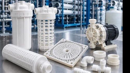
Representative injection molded plastic components for industrial fluid handling and filtration.
Material Selection: PP, PVDF, POM and PA66
Polypropylene (PP) is commonly considered for housings, covers, filter supports, manifolds and fittings where low weight and resistance to many aqueous chemicals are important. It is often an economical option for high-volume components. Its limitations include relatively modest stiffness compared with some engineering plastics, temperature constraints that depend on grade and load, and shrinkage that must be considered when designing broad or dimensionally sensitive parts.
Polyvinylidene fluoride (PVDF) is often evaluated for more demanding chemical-processing and high-purity fluid applications. It can offer strong resistance to a wide range of aggressive chemicals and useful temperature capability, but suitability depends on the exact chemical, concentration, temperature and exposure duration. PVDF grades and processing behavior differ, and its higher material cost means it should be selected where its performance is needed rather than as a universal upgrade.
Polyoxymethylene (POM), also known as acetal, is useful for precision components requiring stiffness, low friction and good dimensional behavior. It may be considered for valve mechanisms, moving guides, pump-related mechanisms, gears and actuator parts. POM is not a default choice for every chemical environment; compatibility with strong acids, oxidizing agents and specific process fluids must be checked against the grade supplier's data.
Polyamide 66 (PA66) can provide high strength, stiffness and wear resistance, particularly in reinforced grades. It may be useful for structural supports, clips, brackets and mechanical components around fluid equipment. However, PA66 absorbs moisture, which can affect dimensions and mechanical behavior. Moisture conditioning, operating humidity and dimensional tolerances should be considered during design.
The comparison is not a universal ranking. PP, PVDF, POM and PA66 have different strengths, and each family includes multiple grades and formulations. A resin should be chosen against the actual fluid, temperature, pressure, mechanical load, regulatory requirements and expected service life.
Engineering plastic pellets for material selection. Conceptual visual, not a resin supplier product photograph.

Chemical Compatibility: Fluid, Temperature and Exposure
Chemical compatibility is one of the first checks for a wetted plastic component. The fluid name alone is not enough. Concentration, temperature, pressure, exposure time, cleaning cycles and mixtures can all change how a polymer performs. A material that is suitable for a dilute solution at room temperature may behave differently when exposed to a concentrated chemical at elevated temperature.
Engineers should identify every fluid that may contact the component, including process liquids, rinse water, disinfectants, cleaning agents, lubricants and occasional maintenance chemicals. Consider whether contact is continuous, intermittent or limited to splashes. Also identify whether the part is exposed to UV light, outdoor weather, steam or thermal cycling.
Chemical resistance charts are useful for initial screening, but they are not a substitute for confirmation from the resin supplier or testing under representative conditions. Stress, molded-in residual stress, weld lines, sharp corners and mechanical fastening can make a part more vulnerable to environmental stress cracking. Where failure could cause leakage or equipment downtime, conduct immersion or exposure tests using molded specimens or representative components and inspect both appearance and mechanical performance.
Structural Design: Wall Thickness, Ribs, Flow Paths and Sealing
A fluid-handling component must balance strength, stiffness, flow performance and moldability. Uniform wall thickness is a useful starting principle because abrupt thickness changes can create uneven cooling, sink marks, residual stress and dimensional distortion. Where thicker sections are required around ports or fasteners, use gradual transitions and review the geometry with the molding supplier.
Ribs can improve stiffness without making the entire wall excessively thick. Their thickness and position should be designed to avoid sink marks and local stress concentrations. Bosses for screws or inserts should be supported with appropriately designed ribs and should not create unnecessarily massive solid sections. Fillets and smooth transitions can reduce stress concentrations, especially around pressure-bearing corners and mounting points.
Flow passages should be designed with attention to pressure loss, dead zones, cleanability and the possibility of trapped air or debris. Thin perforations and narrow slots may be difficult to fill consistently and can be sensitive to flash or dimensional variation. The design should define the required opening size, distribution, open area and allowable variation rather than relying only on a visual reference.
Sealing interfaces deserve particular attention. O-ring grooves, gasket seats, threaded connections and flange faces need drawing-defined dimensions and surface requirements. The sealing system depends on the elastomer, compression, pressure, temperature and assembly method as well as the plastic housing. Avoid assuming that a threaded plastic connection will seal simply because the thread fits. Define the sealing method and verify the assembly under representative conditions.
Representative molded filter baskets, cartridge supports and fluid connection components.

Pressure and Leakage: Design for the Actual Duty
Pressure capability cannot be assigned from polymer family alone. It depends on resin grade, wall thickness, geometry, weld-line position, temperature, chemical exposure, molding quality, assembly loads and the duration of pressure application. A short pressure pulse and continuous operating pressure are different duty conditions. Pressure cycling, water hammer, vacuum and external mechanical loads may also affect the design.
For pressure-containing parts, identify the maximum operating pressure, design pressure, transient peaks, test pressure and expected cycle count. Define the operating temperature range and fluid chemistry at the same time. The design review should examine ports, corners, threaded regions, snap features, insert interfaces and any weld lines that may become weak points.
Leak testing should reflect the product's actual function. Depending on the application, this may involve hydrostatic pressure testing, air-under-water testing, pressure decay, flow testing or a functional test in the assembled equipment. The test method, duration, acceptance criteria and sample frequency should be agreed before production. A successful test on one prototype does not establish long-term pressure life; representative aging and pressure-cycle testing may be necessary for critical equipment.
Injection Molding Considerations: Shrinkage, Warpage, Weld Lines and Tooling
The molding process influences the final dimensions and integrity of fluid handling parts. Semi-crystalline polymers such as PP, POM, PA66 and PVDF shrink as they cool and crystallize. The magnitude and direction of shrinkage vary by grade, geometry, wall thickness, gate position and processing conditions. Tool dimensions should therefore be based on the selected resin grade and validated samples, not on a generic shrinkage assumption.
Gate placement should be reviewed to control flow balance and to keep weld lines away from highly stressed or pressure-critical areas where possible. A weld line may form where two flow fronts meet around a hole, core or insert. Its strength depends on material, temperature, pressure and local geometry. Venting is also important because trapped gas can cause burns, incomplete filling or surface defects.
Cooling should be balanced around thick bosses, ports and large flat surfaces. Uneven cooling can contribute to warpage and changes in sealing-face flatness. Ejection design should avoid distorting thin filter cages or delicate ribs. For threaded components, the mold design must account for thread form, demolding method, draft and the dimensional requirements of the mating connection.
Before mass production, conduct a controlled trial using the intended resin and production-representative process. Check critical dimensions, sealing surfaces, flow openings, thread fit, appearance and assembly performance. Where appropriate, inspect samples after conditioning and repeat checks across cavities and production cycles.
Industrial Applications: Filters, Pumps, Water Treatment and Chemical Equipment
In filtration equipment, molded parts may include cartridge locating bases, filter cages, end caps, perforated plates, support grids, drain manifolds and housing components. Important design requirements include cartridge alignment, open area, resistance to the process fluid, cleaning access and repeatable seating in the vessel.
Pump systems may use molded covers, impellers, internal supports, guards, connectors and fluid distribution parts. These components can experience vibration, pressure pulsation, chemical exposure and mechanical loads. Material and geometry should be evaluated together with the pump's duty cycle and the properties of the fluid.
Water treatment systems may include filter housings, membrane supports, pipe fittings, manifolds and cartridge retention components. Depending on the process, the designer may need to consider disinfectants, cleaning chemicals, water temperature, UV exposure and requirements for low contamination. Food-contact or drinking-water applications require the appropriate grade-specific regulatory documentation; generic statements about a polymer family are not sufficient.
Chemical processing equipment may use PP or PVDF components where chemical compatibility is a priority, but selection must be confirmed for the exact service conditions. Valve bodies, dosing-pump guards, filter drain manifolds and fittings should be designed around the connection standard, installation envelope, pressure duty and maintenance procedure.
Industrial filtration and water-treatment equipment with molded plastic components.

OEM Customization: From Drawing Review to Production
Custom fluid handling components are often defined by the equipment rather than by an off-the-shelf standard. The OEM may need a specific port layout, mounting pattern, filter cartridge interface, sealing groove, flow opening or overall envelope. A drawing-based injection molding project allows these features to be developed around the real assembly.
For an initial review, provide a 3D CAD file such as STEP or STP, a dimensioned 2D drawing, the proposed resin or required performance, fluid composition, operating temperature and pressure, annual demand and expected order quantity. Include mating parts, sealing details and any applicable industry or regulatory standards. If the design is still under development, a sketch, sample or reference photos with key dimensions can help clarify the concept.
The supplier and OEM should agree on critical-to-function dimensions, sample approval criteria, test methods, material traceability and any special packaging or cleanliness requirements. Tooling decisions should consider expected production volume, cavity layout, material shrinkage, gate position, ejection and future design changes. Early DFM discussion can reduce avoidable mold revisions and improve the chance that the first production samples fit the equipment as intended.
How SWKS Supports Custom Industrial Plastic Injection Molded Parts
SWKS supplies custom plastic injection molded components for industrial applications and OEM projects. The website's product range includes PP filter-related components and fluid-handling parts, as well as custom injection molded parts in materials such as PP, POM and PA66. Each project should be reviewed against its own drawing, material specification and operating conditions rather than assuming that one standard design or resin suits every system.
For custom filter supports, drain manifolds, pump-related plastic parts, valve components or other fluid handling products, send the team your 3D drawing, 2D dimensions, fluid details, pressure and temperature conditions, quantity and application description. This information helps establish whether the proposed geometry and material are suitable for a quotation and further engineering review.
For custom industrial plastic injection molded components, please contact our team:
Email: amanda@tjswks.com
Editorial and Technical Note
Material descriptions are general engineering guidance. Chemical compatibility, pressure capability, temperature limits, regulatory compliance and service life must be confirmed for the exact resin grade, component geometry and operating conditions. No universal pressure rating or chemical compatibility claim is made.