


Table of Contents
- Define acceptable shape before the tool is cut
- Read the distortion pattern before choosing a correction
- Review the part and mold as one system
- Use trial data to isolate molding and handling effects
- Verify dimensions after cooling, conditioning and transport
- What should buyers provide for a warpage-sensitive RFQ?
Preventing injection molding warpage starts with defining the shape the assembly needs and the conditions under which it will be measured. This guide follows a practical sequence from drawing review and mold design through trial troubleshooting and production inspection. It is intended for OEM teams sourcing custom industrial housings, covers, brackets and other parts with critical flatness or fit requirements.
Define acceptable shape before the tool is cut
A rectangular machine cover can meet its overall length and width and still rock on its mounting surface. An enclosure may close at three corners while the fourth corner lifts away from the gasket. These are shape and assembly problems that a set of caliper measurements may miss. Start with the functional surfaces: a sealing land, the feet that support a cover, the face that locates a sensor, or the perimeter that establishes a cosmetic gap. Describe the failure that matters and identify which feature controls it.
Agree on the acceptance method with the molder before quoting. Use flatness when the shape of a single surface is the requirement. Where orientation or location matters, relate the applicable control to the functional datums on the drawing. Specify the fixture, support points and any allowed clamping. A flexible panel can appear flat when pressed against a surface plate, while its free shape remains unsuitable for assembly. If the part is intentionally restrained in service, define both the free-state check and the assembled check where they serve different purposes.
Put the measurement timing and environment on the inspection plan. A warm part straight off the machine, a part stabilized at room temperature and a nylon component conditioned to the agreed humidity can give different readings. Use the same method when comparing mold trials, pilot batches and production samples.
See the SWKS guide to injection molding tolerances and part performance for drawing and fit considerations.
Read the distortion pattern before choosing a correction
Record the direction and location of the deformation as well as its magnitude. Put a repeatable coordinate system on the sketch and mark gate location, cavity number, mold side and the affected corners. A diagonal twist calls for a different investigation from a consistent bow along a long edge. A local lift around a boss deserves a different check from a change in the entire sealing perimeter. Photograph the part in the agreed inspection setup, with the scale or instrument reading recorded separately.
Distinguish an overall change in size from a change in shape. An entire part can measure smaller than intended while retaining its profile. Warpage develops when different areas or directions shrink by different amounts, or when the part deforms during release or later handling. Autodesk Moldflow identifies differential cooling, differential shrinkage and orientation effects as contributors. Several can act together, so the shape of a rejected sample is a starting point for investigation.
For a useful comparison, take samples from multiple cavities, identify when each was molded and retain both acceptable and rejected examples. Look for deformation that follows a particular cavity, starts after the mold warms up, or appears only after unpacking. That pattern narrows the likely source and helps avoid changing a process setting that was working well.
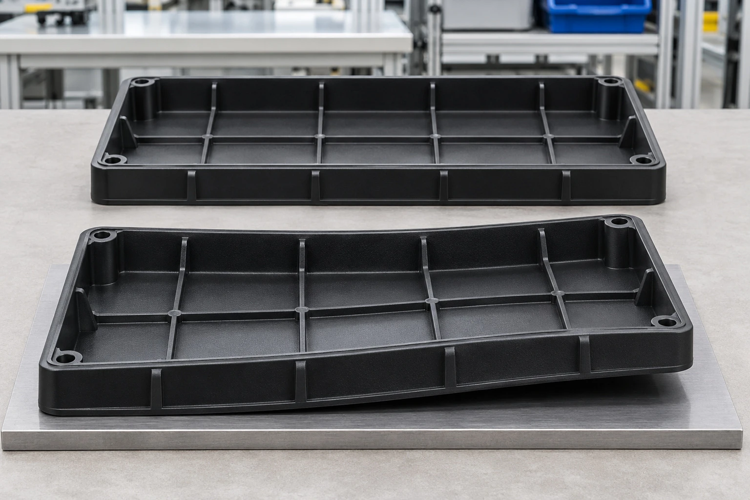
Concept comparison of a bowed molded equipment cover and a flat reference cover. Concept illustration.
| What you see | What to record first | What to review |
|---|---|---|
| One corner lifts on an otherwise flat cover | Map corner heights without clamping and record the gate and mold side | Compare cavity pattern, cooling balance and thickness around the lifted corner |
| Parts look acceptable at ejection and bow after cooling | Measure the same labeled samples at two agreed ages | Check differential shrinkage, conditioning and the storage fixture |
| Only one cavity produces twisted parts | Group samples by cavity at the same point in the run | Compare filling, packing, temperature and ejection for that cavity |
| Parts pass alone but leave a gap in assembly | Check free shape and assembled gap using separate agreed fixtures | Review mating datums, fastening sequence and the tolerance stack |
| Deformation appears after shipment | Compare marked parts before packing and after a representative packing trial | Review stack pressure, support and exposure during storage |
Related SWKS reading on the underlying mechanisms is available in what causes warpage in injection molded parts.
Review the part and mold as one system
In the DFM review, map the wall thickness around the critical face. Look for thick boss intersections, abrupt steps and ribs that join a large flat panel. Consider coring thick features and using gradual transitions. If a cover needs more stiffness, review the rib layout relative to its unsupported spans and mounting points. A rib can stiffen a panel while still creating a local cooling and shrinkage difference at its root. The best arrangement depends on the geometry, load and resin grade.
Review gate options together with flow length, weld-line position, appearance and packing. On a long part, compare near-gate and far-end regions. On a fiber-reinforced part, consider how flow through gates, ribs and changes in section can orient fibers and lead to different shrinkage along and across the flow direction. Compare the same candidate geometry and material across the proposed gate locations so the tradeoffs are visible.
Ask the toolmaker to show how the cavity and core will remove heat from the regions that determine fit. Check how deep features, heavy sections and the far end of a long flow path are served by the cooling circuits. Review ejector placement and the condition of the part during release. A thin cover can be distorted by localized ejector loads when it is still warm. Document any tool changes considered and which measurement they are expected to improve. Where simulation is warranted, compare its predicted distortion pattern with measured parts at trial.
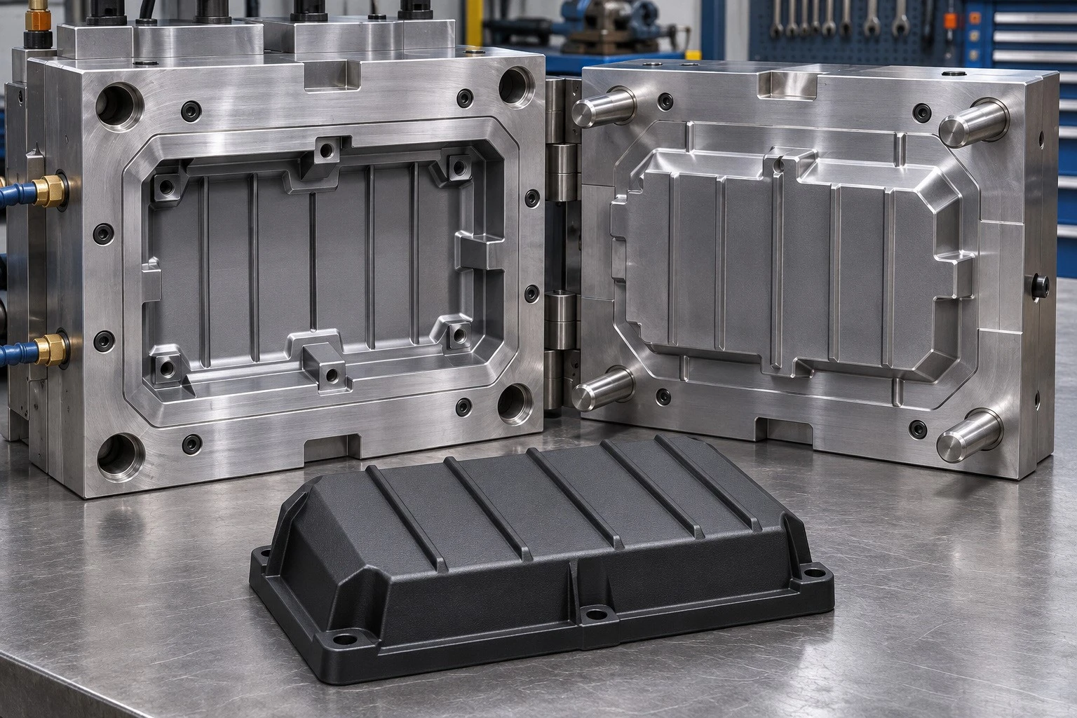
Open injection mold with a molded industrial equipment cover beside the cavity. Concept illustration.
Use trial data to isolate molding and handling effects
Start the trial with the approved material grade and record its conditioning, the machine, cavity and baseline settings. Collect samples once the process has reached stable operating conditions. A single visually acceptable part provides little information about drift across a shift or differences between cavities. Keep the measurement setup consistent and record sample age when inspected.
Choose trial variables that address the observed pattern. If a dimension or part weight responds strongly to changes in hold conditions, review packing consistency and the hold time relative to gate freeze. If deformation grows as the mold warms, compare mold temperatures and cooling circuit conditions before increasing the cycle time. If a part changes shape as it leaves the tool, inspect the release sequence, support and ejection marks. Change one factor at a time where practical, or use a planned trial matrix that can distinguish interacting factors.
Record effects beyond the target dimension. A setting that improves flatness may also move a weld line, change sink, increase flash or change how the part seats. Review the full set of functional requirements with the production material. Confirm that the acceptable settings define a usable operating range and that typical process variation stays within the agreed part limits.
Verify dimensions after cooling, conditioning and transport
Sample the same cavity at agreed points in the production run and inspect parts after the agreed stabilization period. Separate parts by cavity if the tool has multiple cavities. Compare free-state measurements with fit in the actual assembly or a representative gauge. When the relevant requirement is a gasket gap or a sensor mounting angle, measure the functional condition rather than relying entirely on a general length or width.
Keep inspection records that another operator can reproduce. Record which face touched the supports, whether a gauge applied force and which instrument was used. For parts affected by moisture, record conditioning and the interval between conditioning and measurement. If a part passes at molding but fails at assembly, compare the same marked samples before and after storage to determine when the change appears.
Packaging also belongs in the production trial. Wide covers can bend when unevenly supported, and warm parts can take a set if tightly stacked. Evaluate trays, separators and stack height using the expected handling and storage conditions. Repeat the fit check after the packaging trial when transport or warehouse exposure can affect the critical feature.
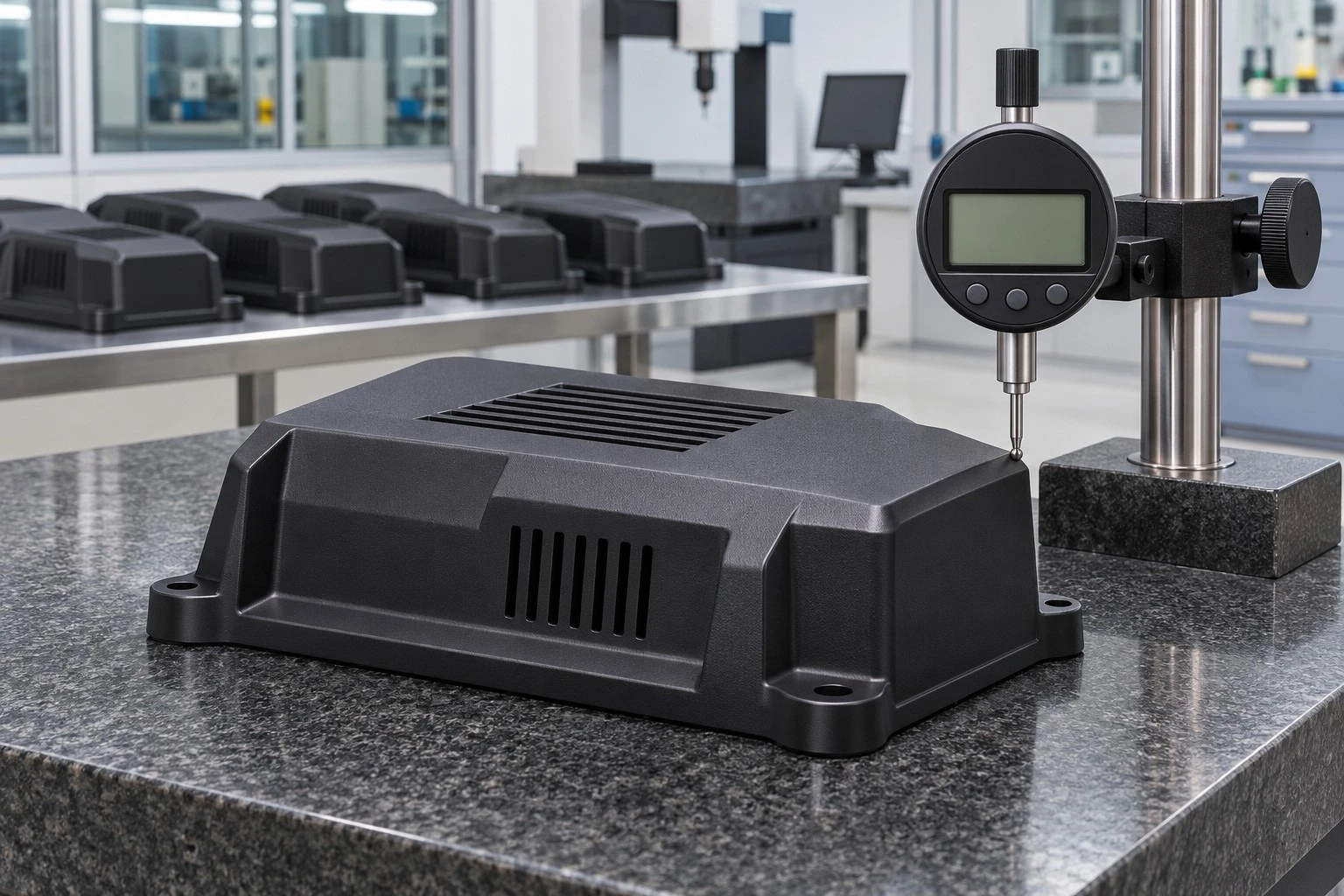
Molded equipment cover checked on an inspection plate with a dial indicator. Concept illustration.
What should buyers provide for a warpage-sensitive RFQ?
Send both the 3D model and the drawing that governs acceptance. Identify the material grade or performance requirements, relevant cosmetic surfaces and the operating environment. Where a mating part controls fit, supply its model, drawing or a representative sample. State which dimensions must be measured on the loose part and which require the assembled condition.
For an existing defect, include cavity identification if available, the inspection method, photos showing the deformation, the time after molding and the measured deviation. A diagram that marks the lifted corner, gate and support points gives the molder a better starting point than a description such as "the cover is twisted." For a new program, define the trial acceptance criteria before steel cutting and decide how a pilot run will represent the expected production conditions.
SWKS can review your drawings, material requirements and assembly interfaces for a custom injection molding project. Send the functional dimensions, estimated order quantity and any existing inspection results with your inquiry. An agreed drawing and inspection method give both teams the same basis for evaluating the first shots and subsequent batches.
Technical reference: Autodesk Moldflow, Contributors to warpage.
For a project review, email your STEP or STP file, dimensioned drawing and quantity to amanda@tjswks.com.