


Tianjin SWKS Technology & Development Co.,Ltd is one of the most reliable manufacturers and suppliers of custom abs industrial instrument display housing in China. If you're going to buy bulk cheap custom abs industrial instrument display housing, welcome to get quotation from our factory. Quality products and low price are available.
The ABS Industrial Instrument Display Housing is a recessed molded body for a panel-mounted digital instrument. SWKS develops the molded component to the customer's design. The product images are generated illustrations of a representative configuration. Contact amanda@tjswks.com for drawing review.
Start at the Panel Cutout
A panel-mounted instrument is often approved against a drawing of the cutout long before the industrial design of the front face is finished. The cutout width, height, corner radius and sheet thickness set the envelope that can pass through the equipment panel. Establish one controlled view looking from the operator side and another from the rear. The first identifies the visible display area and the portion of the edge that covers the panel cutout. The second identifies the clearance needed to attach the clamp and to route the harness. The depth of the housing has to fit the cabinet with connectors fully seated and enough room to unplug them later.
A digital screen usually has an active image smaller than the glass or module body. The drawing should identify the active image boundaries and the usable angle through the housing opening. A design that clears the bezel in a straight-on view can clip part of a character from above or below if the display sits far back. Test sight lines with the tallest panel edges, optional front lens and tolerances in place. A calibrated overlay drawing or a fixture sample gives the purchasing team a more reliable reference than a generic overall screen size for comparing potential housings.
Shape the Clamp and Screen Supports Together
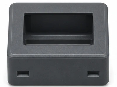
The installed panel thickness sets the usable travel of snap lugs or rear clamps. Include paint, applied overlays and any separately specified sealing strip in that stack. A panel with a rolled lip or formed edge may need a larger keep-out at the back than a flat blank with the same cutout. Discuss how the locking element is released without removing a nearby instrument. Some projects use a separate clamp frame that pushes against the back of the panel. Other installations locate the hardware with rails along the side wall. Choose the fastening direction based on which faces can actually be reached after the cabinet is populated.
The display board should seat on defined pads or bosses. It is possible to position the viewing opening and board mounting holes correctly on the drawing yet lose alignment because a tall soldered component pushes on an internal rib. Include copper-side component outlines or a height map for both sides of the board. Check any connector that sits behind the display for insertion travel with the wiring loom in its normal route. Leave working space for the service operation and document whether the instrumentation assembly is installed once from the rear or will need to be removed as an intact unit.

Match the Appearance to the Viewing Position
An instrument face can be inconspicuous under normal light but show a gloss discontinuity next to the lens at certain viewing angles. For approval, identify the preferred grain and color on a reference sample and define which sides are exposed when the device is in use. Surfaces deeper than the front lip may need different draft as the texture changes. Review how a display lens, printed overlay or user label will be bonded or retained. A lens can reflect light differently if it sits proud of the face or is recessed behind it. Set the actual height relationship with the assembled parts before tool release.
Confirm the Kit in a Panel Trial
Use cutout samples that cover the agreed tolerance range and repeat each check with the selected screen and rear mount installed. Evaluate the fit first without stressing the board and then again when the retaining mechanism is in its final position. Label the trial sample with the panel thickness, cutout and molded cavity identity. Inspect any air gap around the bezel, visible clipping of the display and access to the harness. Document the assembled condition because a bare housing can pass dimensional review while an overlay or mating connector changes the result substantially.
Sample Review and Manufacturing Requirements
The part is made by injection molding to a customer-approved design. For the instrument display housing, the first review covers part orientation, shutoffs around openings and the location of the tooling split relative to the controlled features. Walls that blend gradually into supports generally make shrinkage easier to manage. Draft and radii should be allocated where there is room for them while preserving active contact surfaces and the expected approach direction of the mating parts.
ABS is commonly considered for molded housings that need a defined surface texture and a workable balance of stiffness and impact resistance. High-heat, flame-retardant and standard appearance grades serve different requirements. Review the grade before deciding on the tool because flow, shrinkage and surface gloss vary with the formulation. A color chip is useful for shade approval, and a sample in the final texture gives a more reliable view of how the finish will read across the visible face.
For the inspection plan, separate measurements that can be made on the loose molding from checks that require an assembly fixture or a complete device. This part's key items include view opening, seating face and panel clamp engagement. The plan should state how to locate the sample, how long to condition it before inspection and which instruments or limit samples will be used. Repeat the method on more than one trial part to confirm that the result is consistent and meaningful.
Projects can include panel meters, counter displays, monitoring instruments and machine status indicators. Begin with the installed condition and identify the components purchased as part of the assembly: a display module, lens, panel cutout and rear clamp or carrier. For a replacement or a tooling transfer, record the as-built geometry of the parts that will continue to be purchased. For a new build, a simplified mating model with controlled reference surfaces usually makes the functional dimensions easier to review than an overall envelope by itself.
A deep enclosed instrument body supports the board and takes mounting loads back to the panel instead of relying on a thin decorative bezel. This is worth reviewing with the technician who fits the part, because a design can be dimensionally acceptable but awkward to install. A sample trial should follow the real sequence, including any temporary misalignment before seating. Record where the operator holds the part, where it touches first and which feature indicates the final position.
Production Approval
The panel cutout limits the outer section while the real panel thickness limits available travel in the retaining clamp. A nominal CAD clearance can disappear when the adjacent parts sit at opposite ends of their tolerances. Put both extremes on the review drawing when the fit is tight. Consider which direction the installer can move the component and how its mounting hardware or surrounding equipment limits access. This helps decide which dimensions should be tightly controlled and which can follow a practical molding tolerance.
Agree where the gate can leave a mark and whether that location sees load, contact, sliding or visible wear. Review the part drawing with the proposed flow path in mind so any weld line near an opening can be evaluated on first shots. Where the wall changes abruptly, compare an open ribbed section with a heavier section and decide which shape still fits the assembly. The tooling quotation should identify any feature that needs a side action or a separate insert.
Agree on the smallest meaningful production lot for the initial build and confirm whether parts from different mold cavities should remain identified during evaluation. Use actual assembly feedback to prioritize any remaining dimensional corrections. If the first lot goes into more than one unit variant, document the specific assembly combinations and confirm each before placing repeat orders. Keep approved samples in protective packaging so surface checks can be repeated against a stable reference.
The OEM can then carry out a screen visibility and clamp retention review after the display and harness are assembled. Where operating conditions vary, the useful validation set includes repeat use and samples that cover the functional tolerance range. Compare results against the agreed requirement rather than an impression from the prototype. Retain an approved assembly or representative parts to make later service and repeat-order investigations easier.
Order Details and Drawing Review
| Product | Custom ABS Industrial Instrument Display Housing |
| Process | Injection molding to the approved project drawing |
| Proposed material | ABS in the grade agreed for the operating environment |
| Mating components | a display module, lens, panel cutout and rear clamp or carrier |
| Critical drawing features | view opening, seating face and panel clamp engagement |
| Sample checks | mounting the sample across the minimum and maximum thickness conditions specified for the panel |
| End equipment validation | a screen visibility and clamp retention review after the display and harness are assembled |
| Drawing package | STP, STEP or IGS model and controlled 2D drawing |
Keep the drawing and material decisions on one revision of the purchase record. Before authorizing the tool, agree which dimensions require a report and which checks rely on customer-supplied assembly parts. If the part is intended for more than one product revision, identify which versions the approved samples must fit.
See plastic injection parts and related SWKS design guidance. For pricing and samples, email your drawings and quantities to amanda@tjswks.com.
Hot Tags: custom abs industrial instrument display housing, China, suppliers, manufacturers, factory, bulk, cheap, low price, quotation, Customized OEM ODM Nylon Plastic Parts, household plastic injection parts, lightweight plastic injection parts, PA6 PA66 Nylon Parts quotation, Polyurethane Coated Rubber Urethane Rollers, Small batch injection molding


