


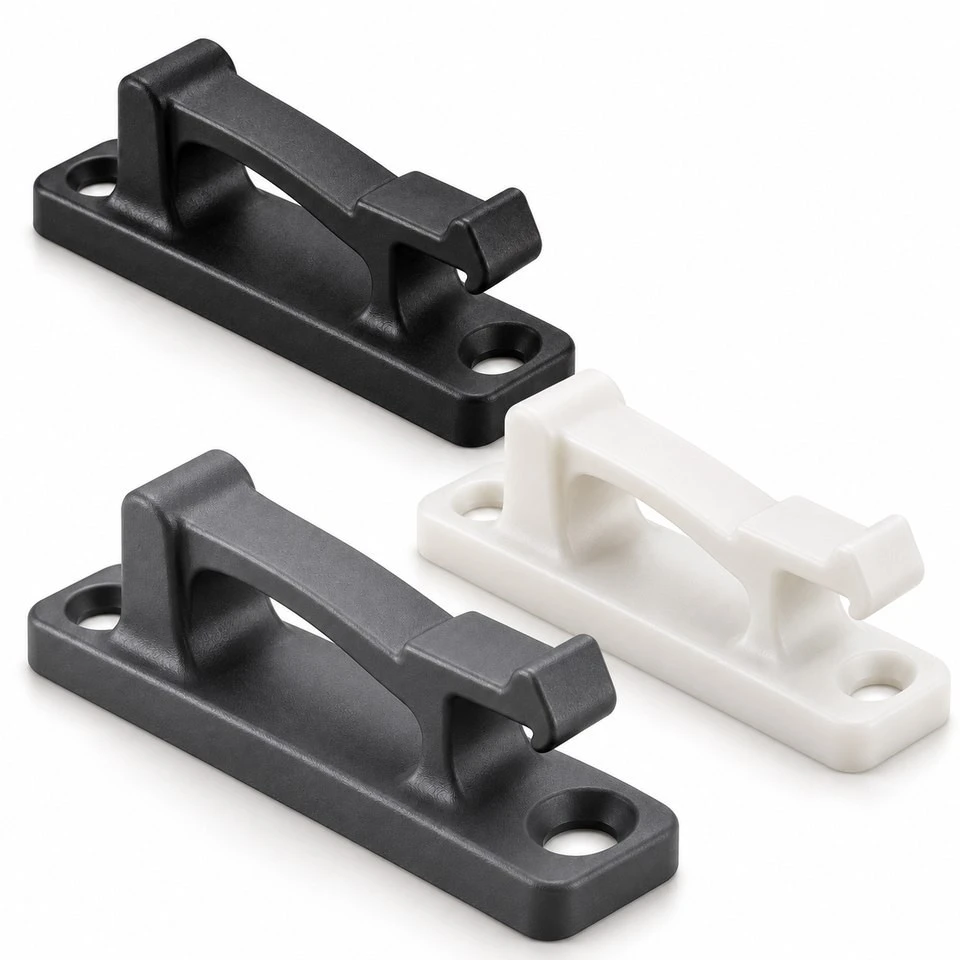
Tianjin SWKS Technology & Development Co.,Ltd is one of the most reliable manufacturers and suppliers of custom injection molded snap fit panel clips in China. If you're going to buy bulk cheap custom injection molded snap fit panel clips, welcome to get quotation from our factory. Quality products and low price are available.
Custom Injection Molded Snap Fit Panel Clips
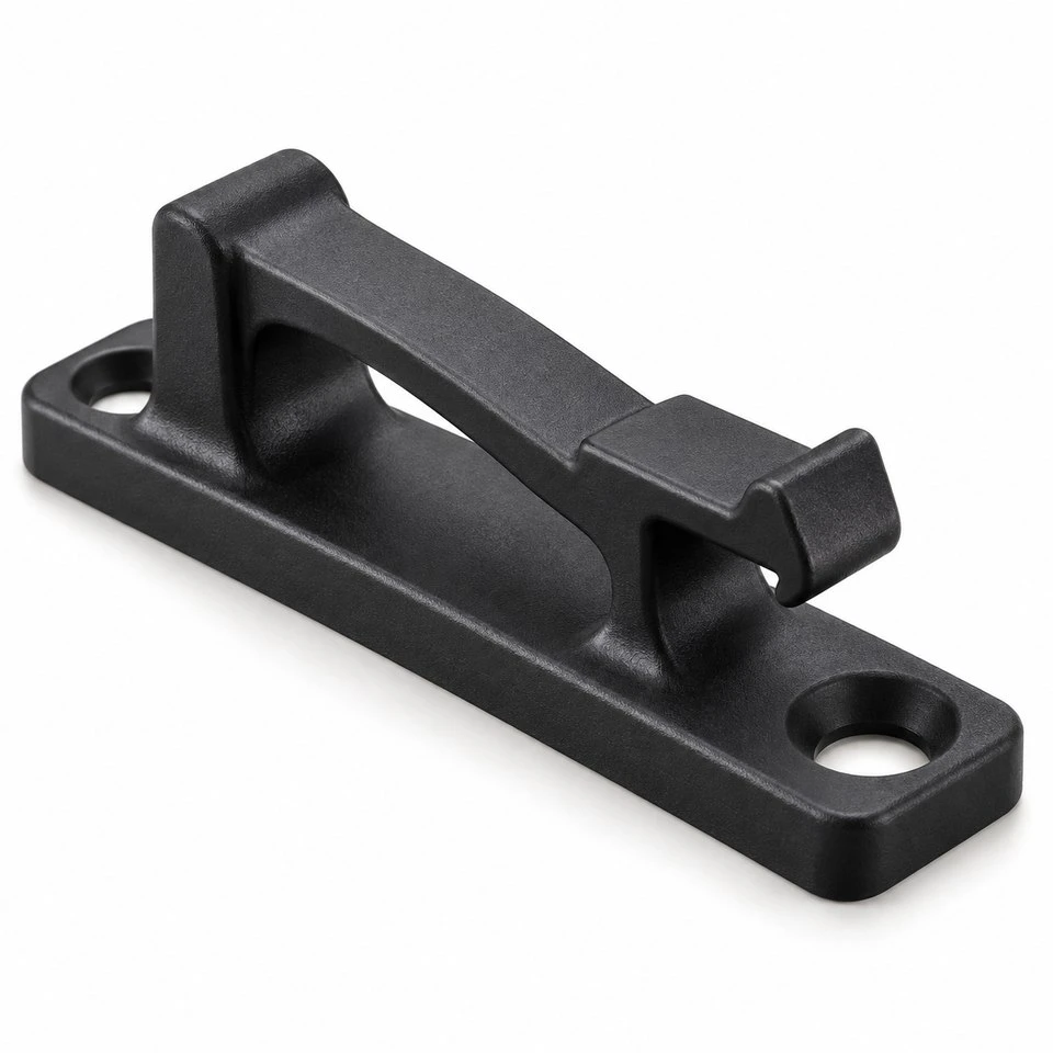
These custom plastic panel clips combine a mounting base, a raised spring bridge and an accessible retention lip in one molded component. They are intended for projects where a removable panel, light cover or equipment trim needs a defined engagement point. The clip geometry, material and installation arrangement are developed around the customer's mating parts rather than selected from a fixed catalog size.
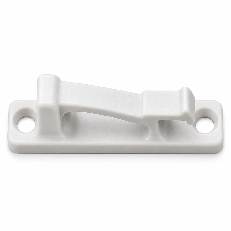
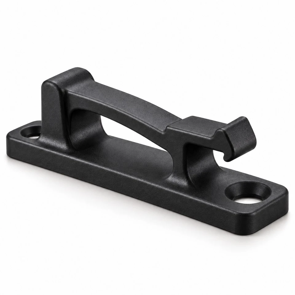
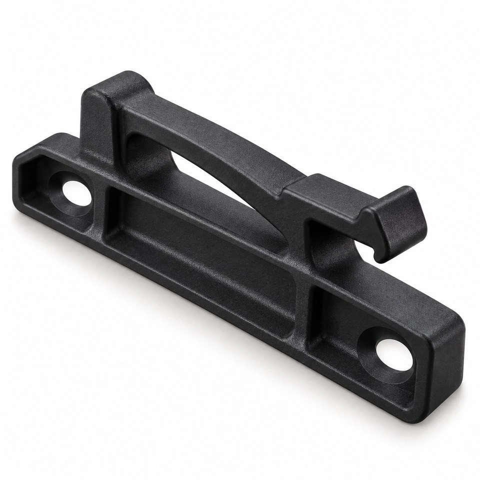
The illustrated concept uses two mounting holes in an elongated base, clearance beneath the raised bridge and a front lip that engages a panel edge. A release area remains accessible for servicing. Different mounting patterns, engagement heights, colors and local features can be evaluated from your drawing. All product images are design illustrations; the final structure and performance must be confirmed for the approved project.
What does this panel retaining clip do?
The clip provides a local retention feature on a machine cover, instrument enclosure or similar assembly. Its base establishes the installation position while the raised bridge places the retention lip above the supporting surface. The mating panel engages at that lip. The available clearance and bridge movement must be considered together with the panel thickness and the access needed for installation.
This arrangement can be useful where the customer wants a serviceable cover with a molded engagement feature. Whether the design replaces another fastener, supplements locating tabs or works with a hinge depends on the assembly. It should not be specified as a structural support without a defined load case and validation. Provide the panel and supporting-frame drawings so that the intended function can be reviewed before quotation.
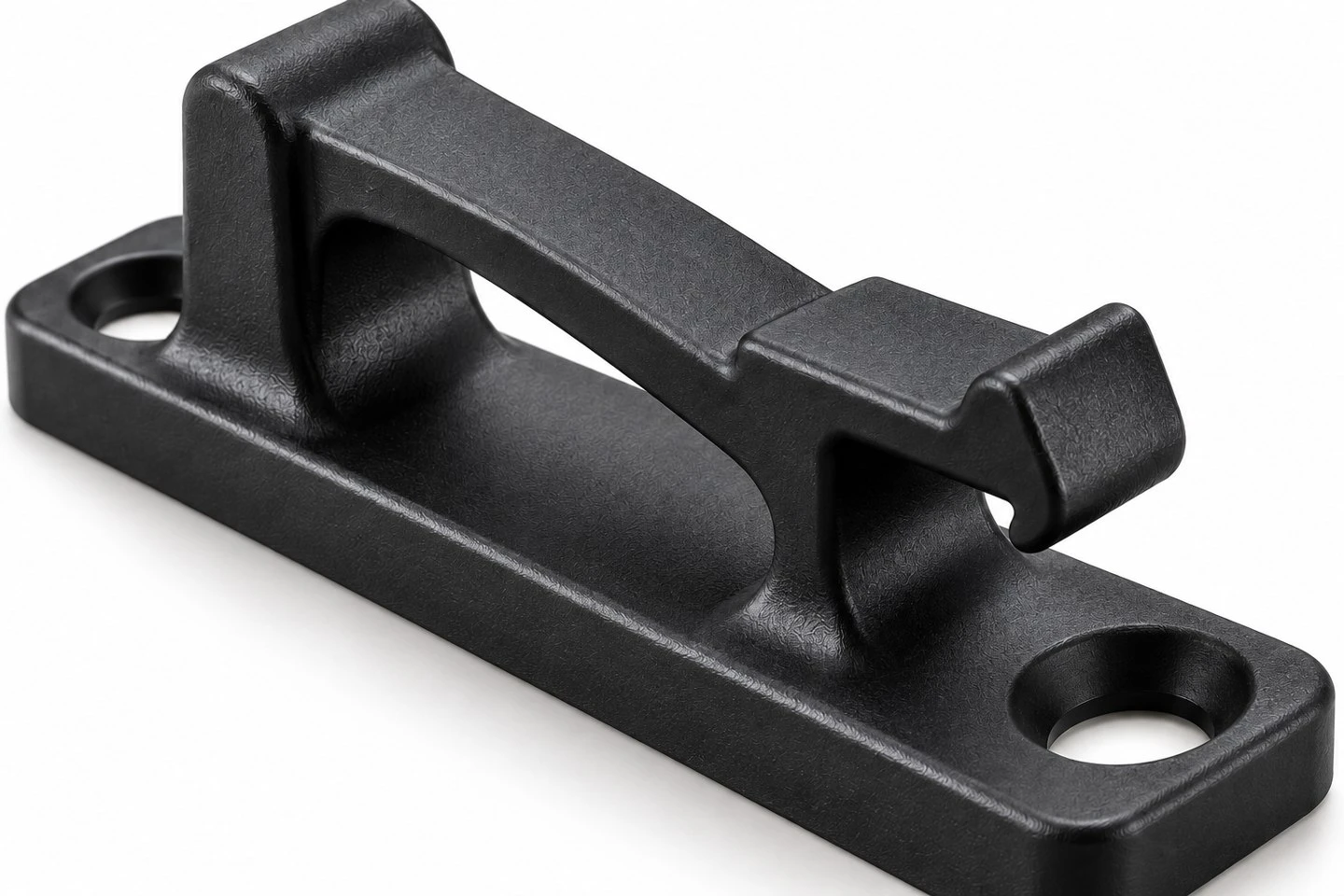
Molded clip geometry concept. Final dimensions follow the approved drawing.
Which dimensions control the mounting interface?
The two mounting holes are part of the functional interface, not decorative details. Their center spacing, bore size and position relative to the retention lip determine where the clip sits on the supporting frame. The base length and width must also leave suitable space for the selected fastening method and any nearby panel features.
Identify the mounting datum and provide the screw, rivet or other attachment requirements. If a screw head needs a recess or a support surface, include that geometry in the drawing. Installation torque and clamping conditions require review for the selected material and base structure. A clip that fits the holes but rocks on its support, interferes with a fastener or shifts the panel engagement is not an acceptable assembly.
| Drawing item | What to specify | Why it matters |
|---|---|---|
| Base envelope | Length, width, thickness and reference surface | Space and support on the equipment frame |
| Mounting holes | Diameter, center spacing and positional references | Alignment with the selected attachment |
| Engagement height | Lip position relative to the mounting datum | Panel location and retained clearance |
| Panel interface | Panel thickness, edge profile and engagement depth | Insertion, retention and service access |
| Bridge clearance | Space beneath and around the moving section | Required movement without interference |
| Release area | Access direction and permitted travel | Controlled removal during servicing |
Dimensions are manufactured to the approved drawing. This product has no universal standard size or fixed performance rating; the table identifies the information needed to define your version.
How are the bridge and retention lip customized?
The raised bridge links the supporting geometry to the lip and provides the intended movement during engagement or release. Its span, thickness, root transitions and available clearance affect how the component behaves. The concept shown has a supported bridge structure, so it should not be treated as interchangeable with every cantilever clip. Your required travel and loading direction determine which arrangement is appropriate.
The lip profile can be reviewed for the approach direction of the panel. A lead-in face can guide engagement, while the retaining face establishes the local contact after assembly. Both need to be evaluated with the actual panel edge, including its radius, coating or forming condition. A drawing of the clip alone may not reveal an interference that appears when the two components are assembled.
Can the clip be opened repeatedly for servicing?
Repeated use is a project requirement that must be specified and tested. Tell us whether the panel is installed once, removed occasionally by a technician or opened frequently. Also identify how the operator reaches the release area and whether a tool is permitted. These details influence the bridge geometry, access space and resin selection.
For sample approval, define the intended insertion and release actions rather than forcing the clip in an unintended direction. If a cycle requirement applies, agree on the test arrangement, material condition and acceptance criteria. Inspect for loss of engagement, permanent change in shape, surface damage and interference with the panel. No cycle-life claim is made from the illustrative product image.
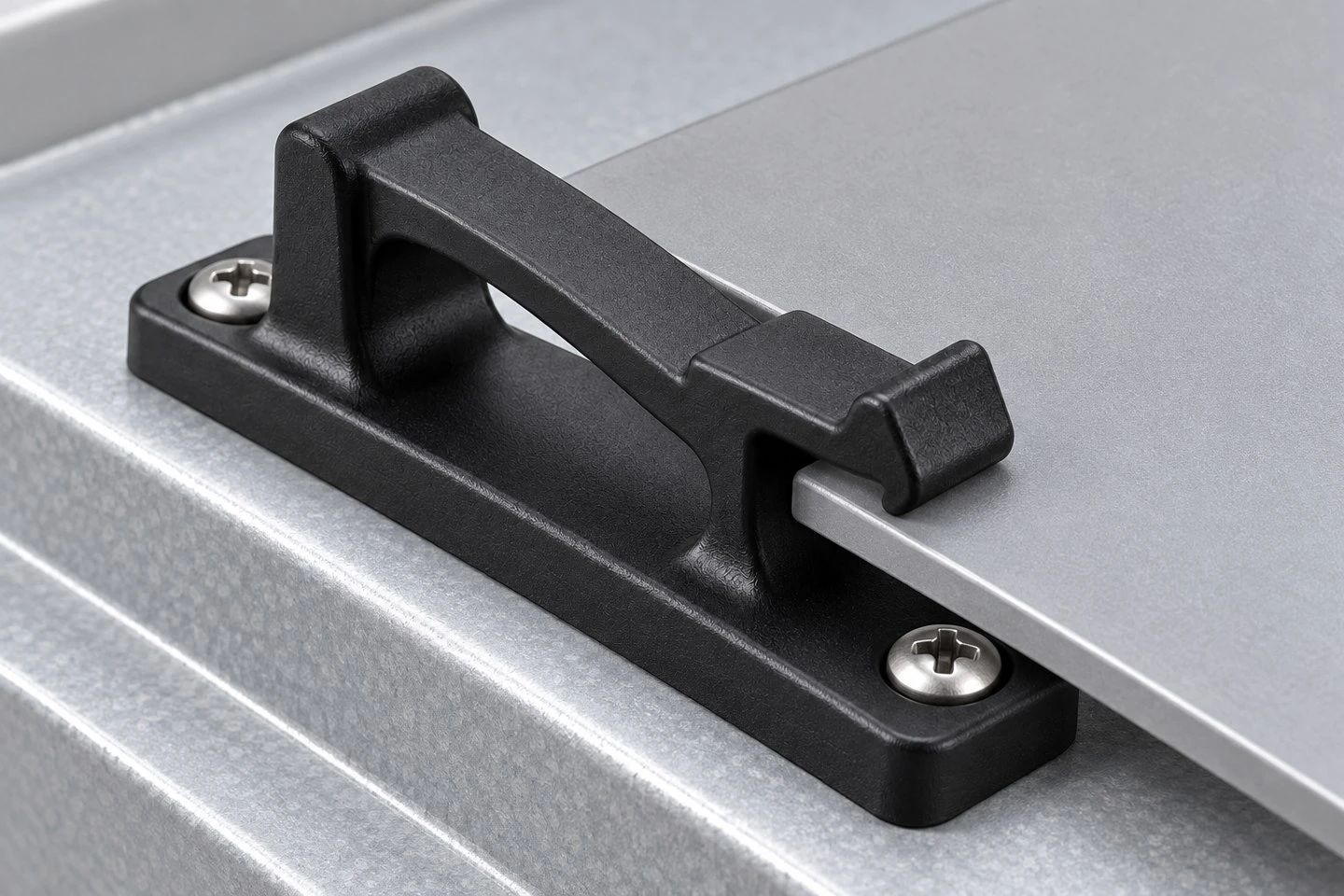
Illustrative panel engagement only; mounting and retention require project validation.
Which plastic materials can be evaluated?
PA, PA66, POM and PP are possible starting material families, depending on the required stiffness, movement, environment and appearance. The exact grade matters. A material chosen for a rigid mounting block is not automatically appropriate for a bridge that must move during assembly. Fillers and other grade differences must be reviewed against that function.
Provide any mandatory material designation and indicate whether alternatives may be proposed. For nylon versions, conditioning and exposure requirements should be agreed when dimensions or assembly behavior are sensitive to material condition. If a project needs a particular chemical, temperature, flame or electrical property, specify the applicable requirement and validation evidence. Such properties cannot be inferred from a generic polymer name or the color of the sample.
What happens when the panel thickness changes?
The engagement height and contact geometry must suit the complete panel-thickness range. A concept that works with one nominal panel can become too tight at one limit or have excessive clearance at the other. Include coatings, edge treatments and any gasket or adjacent layer that contributes to the actual stack-up.
Where the assembly uses several clips, review the combined arrangement. Their positions, panel stiffness and locating features can affect which clip engages first and how the cover is removed. Supplying one isolated dimension does not define the whole fit. A representative assembly model helps identify interference and clarify the dimensional references needed for the clip drawing.
Where can custom panel clips be used?
Potential applications include access covers on light industrial equipment, appliance panels, instrument housings and enclosure trim. A project may use the clip near a hinge, at a removable cover edge or as one element in a larger retention arrangement. The relevant question is whether the proposed interface suits the customer's installation and service requirements.
The application image shows a possible panel-and-frame arrangement only. It does not represent a tested load capacity or an approved installation for a specific machine. If vibration, impact, outdoor exposure or a safety-related retention function is involved, provide those conditions before material and tooling decisions are finalized. The acceptance plan should reflect what the finished assembly must do.
What should be reviewed before the mold is built?
The open bridge, retention lip and hole positions need a moldability review alongside their mechanical purpose. Tool opening direction, draft, parting lines, material entry and ejection must be considered for the actual model. An undercut at the retention feature may affect the tool arrangement. The selected solution should preserve the functional contact surfaces and the intended release movement.
Approve any geometry change through the controlled drawing and model. If a proposed revision moves the lip, changes the hole spacing or reduces working clearance, it also needs an assembly review. A manufacturing change should be accepted for its effect on the product, not simply because it simplifies the mold. Confirm the revised files before tooling starts.
How are color and surface requirements handled?
Black, natural and other requested colors can be evaluated with the selected resin. State whether the clip is visible after installation and provide a reference where color matching is important. The colored images illustrate possible appearances; they do not establish a stocked material grade or a guaranteed match.
Surface requirements should distinguish cosmetic areas from working contacts. The panel contact, release pad and fastener seating areas may have different priorities. If identification marks, a part number or a cavity mark are needed, agree on their position and size before the tool is finalized. Avoid placing raised lettering where it reduces clearance or changes the panel contact.
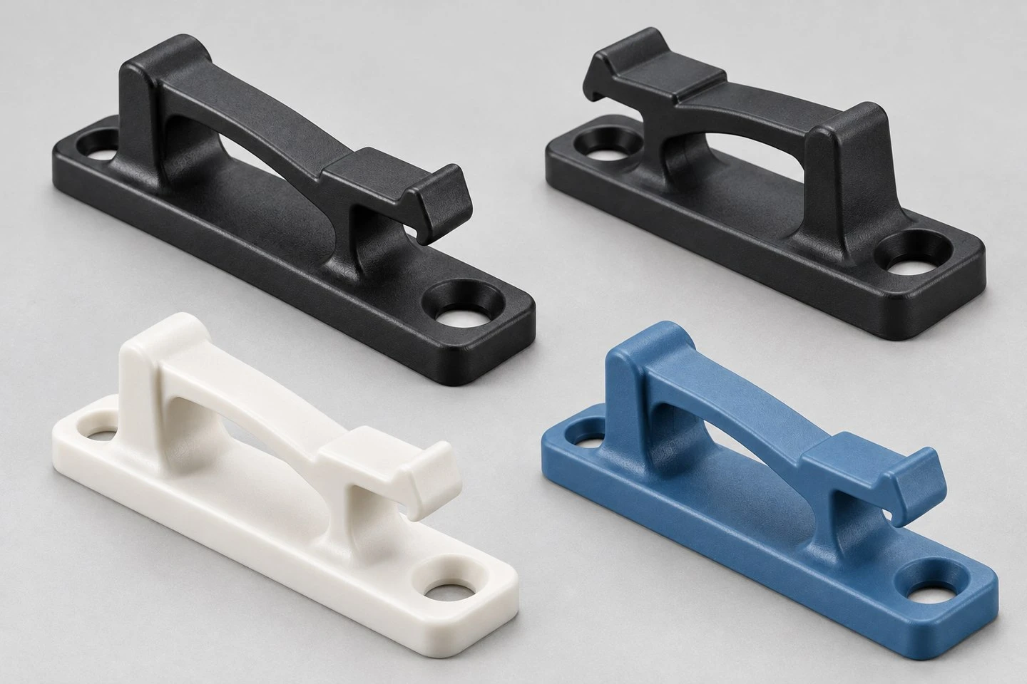
Color and material appearances are illustrative and subject to the selected resin.
What should sample inspection cover?
Inspection begins with the agreed drawing references: base support, mounting holes, engagement height, lip geometry and bridge clearance. Check that the small retention details are complete and that flash or unwanted material does not obstruct movement. Inspect the release area and any surfaces that contact the panel or mounting hardware.
Then assemble representative samples using the intended frame, panel and fasteners. Record installation conditions and verify the specified insertion, retention and release behavior. Where multiple cavities are used, keep the sample identification needed for the agreed checks. A complete-looking clip should still be evaluated for actual fit before mass production is approved.
How are quantities and production scope confirmed?
Send the trial quantity, first production quantity and expected repeat demand. The appropriate mold arrangement, sampling scope and order quantity are assessed from the clip's size, resin and production needs. MOQ, tooling cost, unit price and lead time are confirmed by quotation for the approved design.
Also identify whether the supply scope includes only molded clips or additional work such as marking, sorting or packing by assembly set. Attachment hardware is not included unless agreed. If packaging must prevent contact marks or keep different clip versions separate, state that requirement so it can be included in the production and packing plan.
What do you need to quote this custom clip?
Provide the current 3D file in STP, STEP or IGS format and a dimensioned drawing. Include the material or required grade, color, quantity, mounting method and mating-panel information. Mark critical dimensions and explain the installation and release direction. If an existing clip has failed or fits poorly, identified photographs and a physical sample can help define the problem.
For a useful comparison, request tooling, molded-part pricing and any additional operation as clearly defined items. Confirm the approved revision and inspection scope before proceeding. Our aim is to evaluate your panel-retention design as a complete interface, from mounting base to engagement lip, rather than supply a visually similar clip without understanding how it must fit.
Welcome to send your drawings, material preferences, panel thickness and quantity requirements for a custom injection molded snap fit panel clip inquiry. Contact: amanda@tjswks.com.
Hot Tags: custom injection molded snap fit panel clips, China, suppliers, manufacturers, factory, bulk, cheap, low price, quotation, abs plastic sheet, Custom Cast Urethane Polyurethane Parts, High Temperature TPE Plastic Injection Parts, polypropylene injection molding, Polyurethane Coupling Plum PU Pad, tpe plastic product list


