


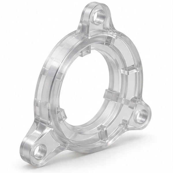


Tianjin SWKS Technology & Development Co.,Ltd is one of the most reliable manufacturers and suppliers of custom pc industrial optical sensor alignment ring in China. If you're going to buy bulk cheap custom pc industrial optical sensor alignment ring, welcome to get quotation from our factory. Quality products and low price are available.
Custom PC Industrial Optical Sensor Alignment Ring
SWKS offers made to drawing injection molding for the optical sensor alignment ring. Send the operating envelope and assembly references with your CAD model so the proposed material grade, molding features and acceptance checks can be reviewed for the intended industrial equipment.
Registering a Sensor Body in an Industrial Mount
This custom PC alignment ring locates an optical sensor relative to the bracket or housing designed by the equipment manufacturer. A ring may use a pilot, shoulder, mounting ears or another defined reference to establish that position. Send an installed section showing the sensor body and the available optical opening. The job is specified around the sensor assembly and its permitted movement. The ring outline by itself cannot establish the direction or accuracy of the completed optical system.
Distinguish the sensor's mechanical mounting surfaces from its viewing or transmitting area. A clear PC grade may be requested for a particular appearance or visibility requirement. If the light path crosses any part of the molding, the designer should provide the optical requirements and the area to which they apply. Where light passes through the center opening only, the main review concerns the mechanical ring and possible interference at the edges of that opening.

Illustrative rendering. Supplied geometry and dimensions follow the approved customer drawing.
Pilot and Shoulder Relationships
A stepped ring can locate the sensor radially and establish its axial position against a shoulder. Show the diameter and length of the pilot, the contact face and the retainer that keeps it seated. A screw pattern may constrain the ring without defining the sensor axis by itself. Identify which features are datums and which provide clearance. The inspection drawing should relate the mounting ears to the functional pilot rather than to an arbitrary outside edge.
The sensor body may be supplied in more than one revision or diameter. Provide its controlled drawing or manufacturer's mechanical envelope for the intended version. An adapter accepted with one sensor can require review when another variant is introduced. Note any cable connector that constrains rotation. A useful section includes the surrounding bracket, sensor body and fastener heads so the supplier can see the actual mounting space available to the molded ring.
PC Grade and Surface Condition
The resin specification should identify the PC grade and color formulation used for the project. Transparent material can show molding flow or tooling witness marks differently from an opaque grade. State what region must remain visually clear and what viewing condition is used for acceptance. If the part only needs to locate a sensor, set appearance criteria that reflect that function. Grade data and a representative molded sample can support the customer's review.
Polycarbonate projects should identify contact with cleaners, oils and other agents at the mounting location. Provide the chemical names and use conditions along with humidity and temperature exposure. The installed ring can carry strain from its retention method, so material evaluation should use the relevant fitted condition. The equipment owner defines optical, chemical and mechanical qualification requirements. The supplier can identify which checks are included in the molded component inspection and which are performed in the sensor system.
| Project item | Information for review |
|---|---|
| Material | PC grade subject to application approval |
| Process | Custom injection molding |
| Key drawing features | pilot diameter, locating step and mounting ear position |
| Mating assembly | the sensor body, mounting bracket and optical clearance |
| Drawing formats | STP, STEP and IGS |
| Dimensions and operating limits | As specified on the approved drawing and qualification plan |
Tooling a Clear Ring With Controlled Datums
The mold layout must accommodate the annular section, pilot step and mounting ears. Thickness transitions near a screw boss can influence local shrinkage and the position of a shoulder. Gate, ejection and mold split locations can be reviewed against the sensor envelope and appearance zones. If a draft adjustment changes the useful pilot engagement, show its effect in section before approval. The customer can then confirm whether the proposed molded surface still establishes the intended location.
A measurement of the outside ring alone may miss a change in the functional pilot. Check the dimensions and profile identified by the released datum scheme. If a contact gage or fixture represents the sensor, name that reference and retain its drawing. A noncontact method can be useful for certain shapes, but the technique and part orientation should be stated so readings from clear material can be compared on the same basis. Sample reports can retain cavity identities and representative photographs.

Illustrative rendering. Supplied geometry and dimensions follow the approved customer drawing.
Alignment Assessment in the Instrument
The equipment owner can install molding samples with the approved sensor and fastening arrangement. A first check establishes whether the ring seats fully on its bracket and allows the intended adjustment. The completed sensor system can then be evaluated using the owner's optical target, position or alignment procedure. Record the configuration and any manual adjustment made during the trial. The component drawing and system acceptance record should identify the same sensor version.
If an observed alignment issue appears after cleaning or maintenance, inspect the seating shoulder and bracket before comparing material lots. Residue, a changed fastener or an incorrectly oriented ring can affect the installed result. Document the condition found and the contacts made by the hardware. For a new ring revision, retain before and after position records using the same system setup. These observations help the designer decide which mechanical dimensions need a controlled limit on repeat supply.
Orientation and Light Path Access
The mounting can be checked from several approach directions where the sensor requires access to a target. Include the adjustment range and the position of any shield or cable guard. A mounting ear that clears the housing at one angle might constrain another orientation. The designer can show allowable positions in the released assembly model and identify any side that must remain accessible during service. Inspect the actual aperture edge where it is close to the working path.
If molded markings are needed, reserve an area that does not enter the optical opening or interfere with the mounting faces. A cavity symbol, part reference and orientation mark can serve different purposes. State which are mandatory and which may be carried on packaging. Protect clear surfaces against rub marks during shipment when the acceptance specification requires them to retain their initial finish.
Dimensions Supplied With the Quotation Request
For this optical sensor alignment ring, identify pilot diameter, locating step and mounting ear position on the released component print. A solid model conveys the nominal shape. The accompanying dimensioned views identify the limits and the references used for acceptance. The quote request can highlight a small number of characteristics that drive assembly performance, then state which other dimensions follow the agreed general tolerances. Where a characteristic is evaluated using a fixture, provide that fixture reference or agree a representative setup before the first samples are reported.
Bring the adjacent geometry into the review by including the sensor body, mounting bracket and optical clearance. Note the part numbers or model revisions used in the current installation. Purchased hardware can have its own tolerances, which should be considered when evaluating the molded interface. If multiple equipment versions are covered by one order, distinguish each version and show which mating combination applies. The sample plan can name the build that the customer will use for the first fit assessment and the other variants that require a later check.
Approval Samples and Repeat Supply
The proposed PC grade, pigment and accepted drawing revision should be stated with the trial. The buyer and molding team can agree sample quantities, cavity identification and reporting format before molding. Describe sensor registration, seating and inspection coordinates in the sample request so the trial can use the intended setup. Keep the difference between a free part measurement and a measurement after mounting visible in the inspection record. For dimensions that depend on conditioning, record the condition and time associated with each reading.
A production release can retain a labeled reference sample, the agreed report and notes from the assembly trial. If a later purchase uses the same part number, attach the approved revision instead of relying on a photograph or a short description. State any change notification requirements for resin, tool or secondary operation. A controlled revision makes it possible to identify which earlier samples represent a later lot and what has to be rechecked when the interface changes.
Packing and Project Planning
Packaging should protect the functional surfaces identified on the optical sensor alignment ring drawing. Identify whether contact with neighboring pieces could mark a locating edge or deform a slender feature in storage. Bulk bags, divided trays and individual separators serve different handling needs. State the expected packing quantity and labels required at receiving, including customer reference, revision and manufacturing lot when specified. The packing method can then be considered with the unit quote and the planned shipment schedule.
Provide the expected sample milestone, order quantity and repeat demand along with your STP, STEP or IGS drawing. Tooling cost, sample production, molded unit price and any approved bought in items can be quoted in their own lines. Where the geometry needs a moldability adjustment, the proposed change should be shown to the drawing owner before tool release. Commercial lead time and delivered performance are confirmed for the approved design and agreed production program.
Receiving Inspection and Revision Records
At receiving, use the approved print to identify which measurements establish acceptance for the optical sensor alignment ring. Record the quantity sampled, the measured condition and the method used. A single drawing may require an ordinary dimension check on a mounting feature and a different assembled check on the operating interface. Provide a sketch or photograph of the measuring setup if it is difficult to describe in one note. This helps the supplier and customer compare readings that refer to the same physical feature.
The retained reference should include sample identification and the release date alongside the drawing revision. If the buyer later reports a fit change, photographs of the installed component and the mating hardware can be compared with that record. List any maintenance or hardware changes that occurred between the accepted trial and the reported condition. The resulting evidence supports a focused review of pilot diameter, locating step and mounting ear position and the production lot involved.
Request a Custom Molding Quotation
Explore our plastic injection parts and engineering plastics selection guide for related applications. Email your drawing, required grade and quantity to amanda@tjswks.com or call 0086-15222707659.
Hot Tags: custom pc industrial optical sensor alignment ring, China, suppliers, manufacturers, factory, bulk, cheap, low price, quotation, Custom Cast Urethane Polyurethane Parts, design injection molded plastic parts, household plastic injection parts, Injection Molded Polypropylene Parts, Nylon Products For POM Machinery Plastic Products, opaque plastic injection parts


