


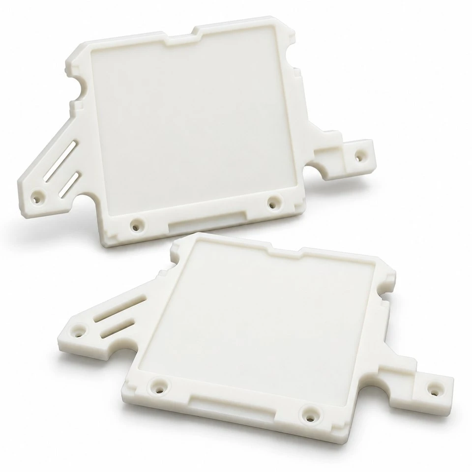
Tianjin SWKS Technology & Development Co.,Ltd is one of the most reliable manufacturers and suppliers of custom pom mounting plates for electronic equipment in China. If you're going to buy bulk cheap custom pom mounting plates for electronic equipment, welcome to get quotation from our factory. Quality products and low price are available.
Custom POM Mounting Plates for Electronic Equipment
A compact electronic assembly often needs a plastic component that does more than cover an opening. It may have to position an internal module, clear nearby connectors, receive several mounting screws and fit an enclosure with limited space. SWKS offers custom POM mounting plates developed around these mechanical interfaces. Instead of adapting your equipment to a standard rectangular plate, the outline, recesses, mounting ears and clearance features can be designed around your drawing and assembly layout.
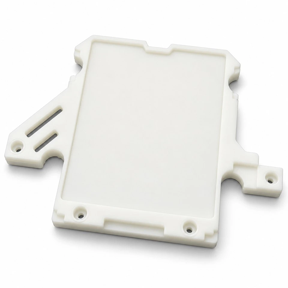
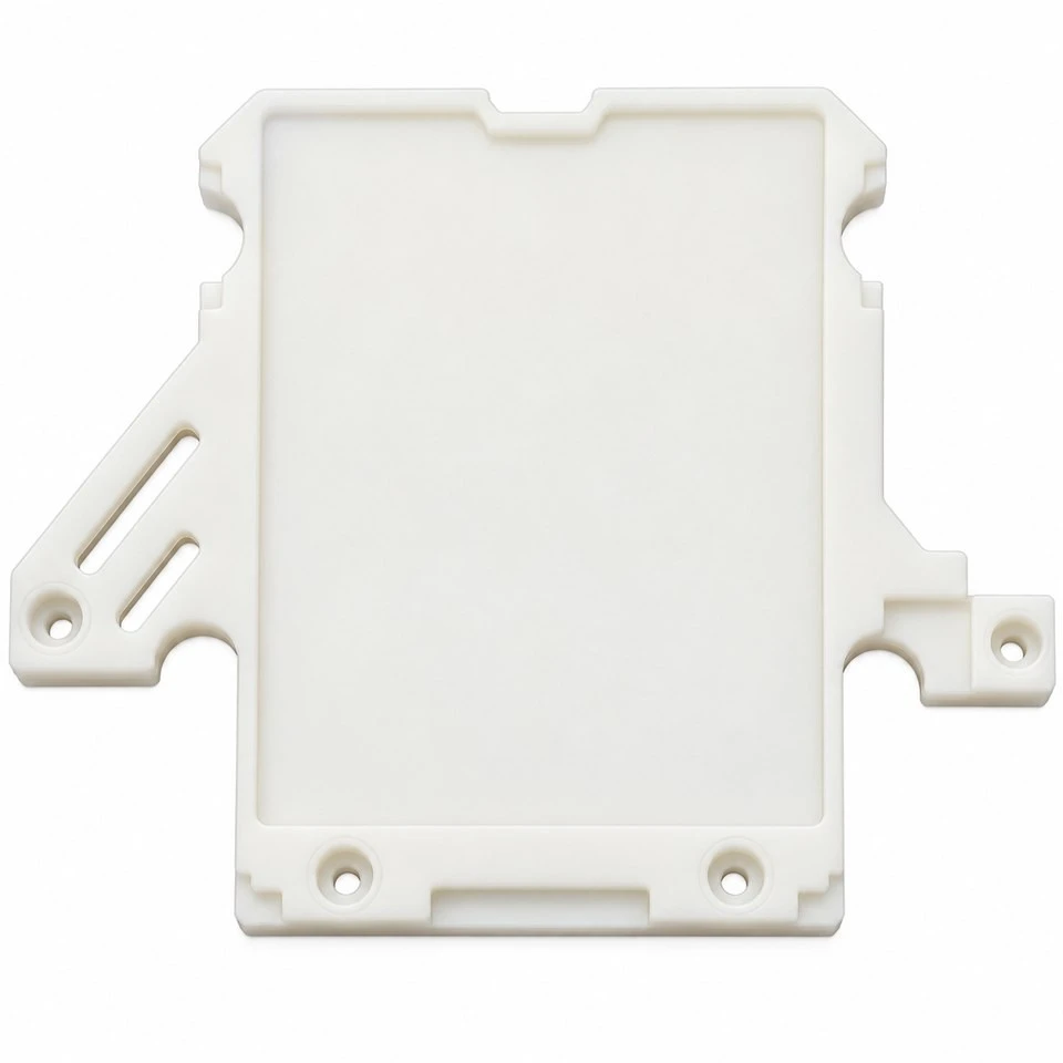
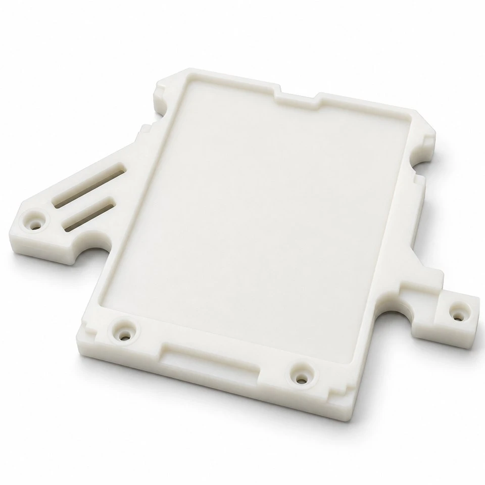
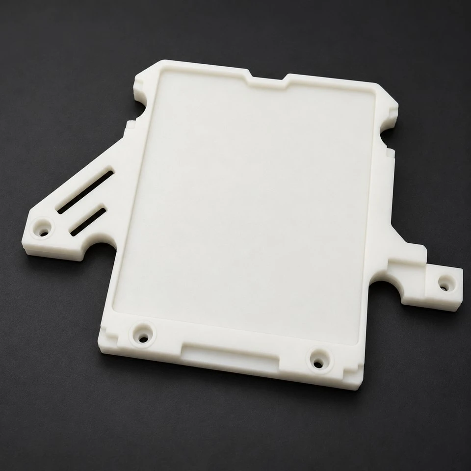
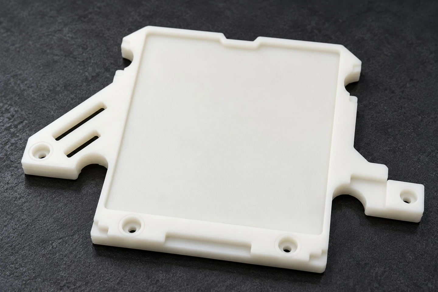
The illustrated design has a broad recessed central face, a shallow perimeter lip, asymmetric side extensions, elongated slots and recessed screw locations. These features demonstrate a possible mounting or carrier structure for electronic equipment. The exact function is determined by your assembly design. This is a custom manufacturing product, with dimensions and material specifications agreed for each project; the photographs do not establish a universal model or a verified electrical performance rating.
What role can this plastic mounting plate serve?
A mounting plate can provide a repeatable mechanical reference inside an enclosure. Its locating edges may align a module during installation, while the screw pattern secures the plate to a frame or another component. Recessed areas can accommodate mating features or create defined clearance zones. Depending on the final design, similar components may be considered as internal carrier plates, equipment interface plates, fixture bases or protective intermediate components in electronic assemblies.
These possible uses should be checked against the complete equipment. A shallow tray-shaped part does not automatically act as a sealed housing, heat sink or electrical shield. If a circuit board will be mounted above it, the board support locations and clearance to solder joints need to be specified. If the component separates conductive parts, the equipment designer must define the applicable electrical requirements. We manufacture the agreed mechanical geometry and review the material against the stated specification.
Which features of the illustrated plate can be changed?
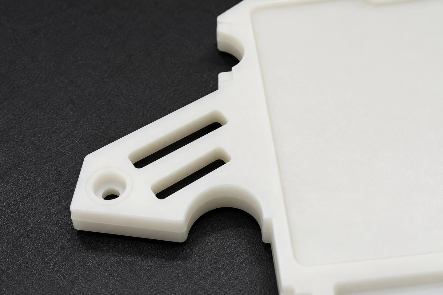
The central recessed area can be adapted to the footprint of a module, cover, mating plate or other assembly component. Its depth, corner shape and surrounding lip should reflect the function of the interface. A lip used only for positioning has different requirements from an edge that carries a sustained load. Please identify the surfaces that actually touch the mating component so that unnecessary contact and assembly interference can be avoided.
The side ears can be revised to suit your fasteners and available installation space. Open slots, elongated openings, semicircular cutouts and stepped edges can provide access or avoid nearby features. Their purpose should be explained in the drawing or assembly model. If a feature is intended to adjust position, specify the adjustment direction and range. If it is intended for ventilation, cable routing or a separate retaining part, provide that requirement rather than relying on the appearance of the opening alone.
Why consider POM for an electronic equipment mounting plate?
POM, also called acetal, is an engineering thermoplastic considered for components where mechanical stiffness, dimensional behavior and sliding contact are relevant. In a mounting plate, the useful properties depend on the selected grade, wall structure, mounting method and working environment. The material is therefore reviewed together with the geometry. A broad flat panel, a locally loaded fastening ear and a sliding locating surface present different design questions even when they belong to the same component.
Share the actual temperature conditions, any contact with cleaning agents, the expected mechanical load and the installation environment. If the part operates near a heat-producing module, provide the local temperature rather than only the room temperature. A resin family name cannot establish the allowable working temperature of the complete assembly. We can review a proposed grade and the available supplier data, then agree what needs to be confirmed through sample evaluation.
Does milky white POM mean the part is antistatic?
No. Color and appearance do not establish antistatic, static dissipative or conductive performance. The reference concept is associated with an ESD antistatic POM description, but a production order must identify the actual resin grade and the required electrical behavior. Ordinary POM and modified POM formulations should not be treated as equivalent. If electrostatic control matters to your equipment or production process, include that requirement at the quotation stage.
Define whether your specification concerns surface resistance, surface resistivity, volume resistance or another measured property. Provide the required range, test method, conditioning environment and the locations to be tested on the molded component. These are distinct measurement requirements, so a general request for "ESD plastic" is not enough to define acceptance. The selected grade, molding conditions and part design may affect the finished result. Any ESD performance claim must be supported by the agreed material documentation and relevant finished-part testing.
Also explain how the component participates in your electrostatic control arrangement. A material property alone does not prove that an assembled device controls charge as intended. Where the application requires a discharge path, the interfaces and complete assembly need evaluation. We do not assign an unsupported ESD rating to the white concept images, and we do not infer flame resistance or electrical insulation approval from a POM designation.
Can nylon, ABS or PP be used instead?
Alternative resin families can be evaluated if the project calls for a different balance of structure, appearance, processing or environmental compatibility. Nylon may be considered for mechanically demanding features, with moisture conditioning included in the dimensional discussion. ABS may be reviewed for indoor equipment components where appearance and molded geometry are relevant. PP can be considered where its particular grade properties suit the application, while sustained fastening loads and panel stiffness still need review.
Changing resin is a design decision rather than a simple color substitution. Shrinkage, warpage behavior, stiffness and assembly response may change, and the mold may require a different allowance or revision. If both POM and another resin are being considered, tell us before tooling starts. We can then review the proposed material routes with your design instead of assuming one cavity will produce identical dimensions in every polymer.
| Project item | Information to specify |
|---|---|
| Primary material | POM grade or required properties; alternatives can be reviewed |
| Appearance | Milky white, natural or another agreed color and surface finish |
| Geometry | Outline, recessed area, mounting ears, slots, cutouts and locating edges |
| Critical interfaces | Mounting centers, mating faces, clearance zones and assembly datums |
| Special requirements | Exact ESD, flame, electrical or environmental specification when applicable |
| Dimensions and quantity | According to the approved drawing and quoted order requirements |
How are mounting holes, slots and clearances defined?
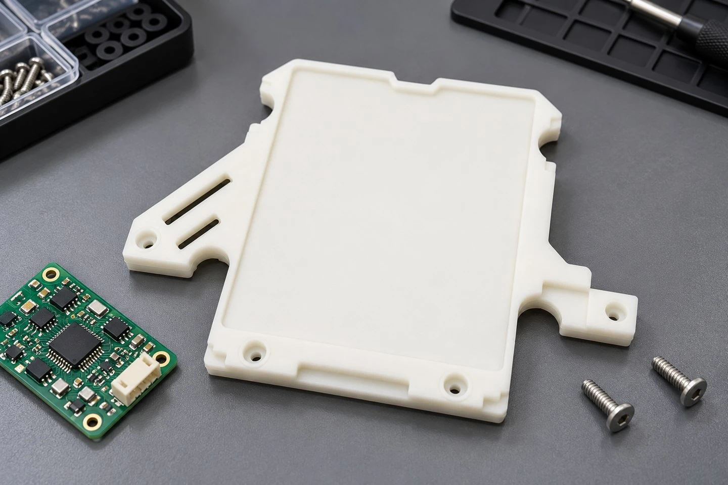
The fastener arrangement should start from the equipment interface. Provide the screw type, head envelope, mating surface and access direction. A recessed hole should accommodate the specified fastener without leaving an unintended protrusion or creating excessive local stress. If a metal sleeve, washer or insert is required, identify it separately. Such hardware is not implied by the recessed holes shown in the illustrative design.
For elongated slots, state whether they provide positional adjustment, clearance or access. The slot width and end radii must suit that function. For cutouts around connectors, brackets or adjacent components, share the maximum mating envelope and the assembly sequence. Clearance during installation can differ from clearance after the equipment is assembled. An assembly model is especially useful where several components approach the plate from different directions.
What dimensions should be included in the drawing?
At minimum, define the overall envelope, central recess dimensions, nominal thickness, mounting-hole diameters and center locations. Include slot lengths and widths, ear positions, cutout radii and any height steps that control fit. Identify the primary locating face and the surfaces from which critical dimensions are measured. Where flatness or parallelism affects the assembly, specify the relevant area and inspection condition.
This product does not have a fixed standard dimension table. A photograph cannot establish accurate scale or hidden geometry. We quote the requested dimensions from an approved drawing and discuss tolerances in relation to the resin, mold design and inspection method. If only a sample is available, it can support the development discussion, but the final production definition still needs agreement. Please mark critical dimensions instead of imposing the same tight tolerance on every nonfunctional edge.
How is a broad plastic plate prepared for injection molding?
A large central face with several side extensions needs attention to wall distribution and cooling. Thick sections around recessed fasteners can behave differently from a thinner panel. We review transitions, local ribs, corner radii and feature spacing to identify areas that may benefit from adjustment. The objective is to preserve the required assembly interfaces while developing a practical molded structure.
Gate position, parting line and ejection are reviewed together with the visible and functional surfaces. A gate vestige should not obstruct a locating edge or interfere with a mating component. Ejector marks and permitted parting-line traces should be addressed in the acceptance criteria where they matter. Features that prevent straight mold release may require side actions or a revised design. These decisions are evaluated from the complete model rather than inferred from a single top-view photograph.
What is checked during the sample approval stage?
The first review connects dimensional inspection with assembly fit. Check the plate against the intended enclosure or fixture, install the specified fasteners and confirm access around the mounting ears. Evaluate the central recess with the actual mating part. Confirm that slots and cutouts provide the intended clearance throughout installation and service. If a board or module sits above the plate, verify the support arrangement and the required distance to surrounding features.
Special performance requirements need their own agreed checks. A dimensional report does not establish ESD behavior, flame classification or service life. Define any material identification, electrical testing, temperature exposure or mechanical evaluation that the project needs. After approval, retain the drawing revision, resin specification, color reference and agreed sample criteria as the production baseline. Changes to any of these items should be reviewed before another batch is produced.
What affects tooling, minimum order quantity and price?
Tooling and unit price depend on the component envelope, mold complexity, material grade, cavity arrangement, order volume and inspection scope. Side features and special surface requirements can change the tooling approach. A specialty ESD formulation may also require different sourcing and verification from a general-purpose material. Please identify these needs before quotation so that the proposal includes the relevant work.
Minimum order quantity and production timing are confirmed for the individual project. Provide the initial quantity, expected annual demand and any planned versions. If several plates share an outline but have different mounting patterns, send the complete version list. We can review whether interchangeable tooling elements are practical or whether separate tooling is more appropriate. Tool development, sample evaluation and production approval are included in planning for a new custom component.
How can you request a quotation for your equipment plate?
Send a STP, STEP or IGS model with a dimensioned drawing when available. Add the preferred material, color, required quantity and a short description of the assembly. If your requirement involves antistatic POM, include the exact electrical specification and testing expectations. If the material has not been selected, describe the operating conditions and critical interfaces so that suitable candidates can be discussed.
SWKS can review custom injection molded mounting plates with recessed panels, slotted ears, clearance cutouts and locating features for electronic equipment projects. The final product is manufactured to the agreed drawing and project specification. Welcome to send your drawings, material requirements and required quantities for an inquiry. Contact: amanda@tjswks.com
Hot Tags: custom pom mounting plates for electronic equipment, China, suppliers, manufacturers, factory, bulk, cheap, low price, quotation, pom absorber parts, pom baffle parts, pom grinding parts, pom molding, pom mounts, pom polishing parts


