


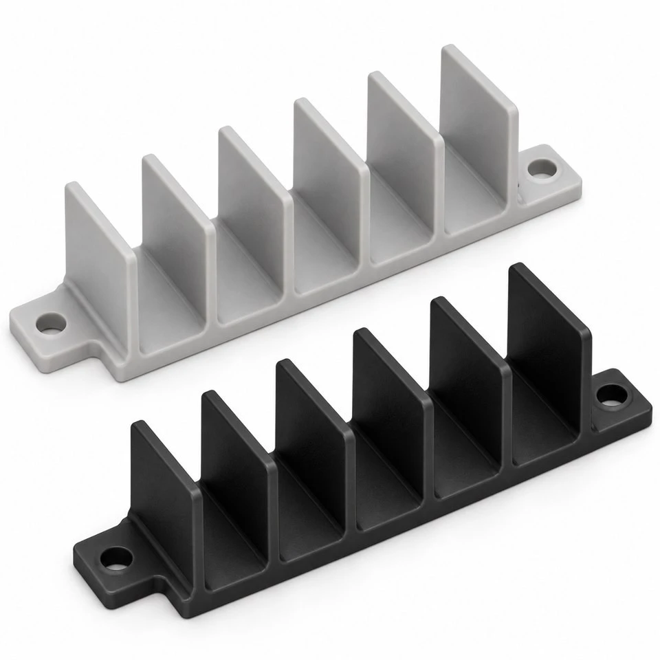
Tianjin SWKS Technology & Development Co.,Ltd is one of the most reliable manufacturers and suppliers of custom nylon terminal separator barriers in China. If you're going to buy bulk cheap custom nylon terminal separator barriers, welcome to get quotation from our factory. Quality products and low price are available.
Custom Nylon Terminal Separator Barriers
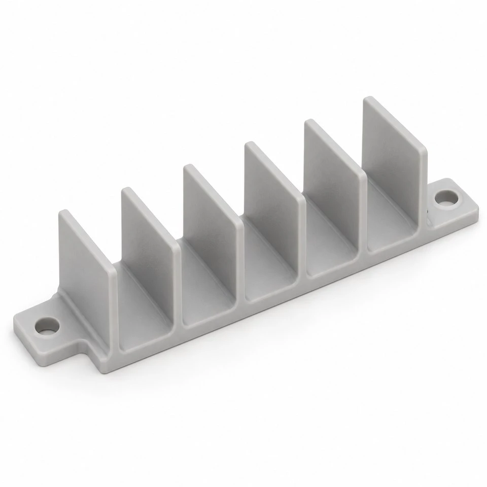
A terminal area needs room for conductors, tools and inspection as well as a place to attach hardware. When those requirements are squeezed into a compact enclosure, a custom molded partition can help organize the layout. SWKS offers nylon separator barriers developed around the customer's terminal arrangement. Upright walls, an attachment base and locating features are combined into a single molding. Send the internal layout to amanda@tjswks.com so the physical interfaces can be reviewed before tooling.
Material: ABS/POM/PA66/PP/PC/PA/PU/TPE/TPU etc.
Processing Service: Injection
Drawing: STP/STEP/IGS
Contact: amanda@tjswks.com / 0086-15222707659
What is the purpose of a terminal separator barrier?
The component provides a series of physical partitions around an equipment-specific connection area. Each wall can define a boundary between neighboring positions, guide an assembly operation or keep a loose conductor from crossing directly into an adjacent space. The exact purpose should be stated on the project drawing. A barrier intended only to organize assembly may need a different geometry and verification process from one assigned an electrical insulation role.
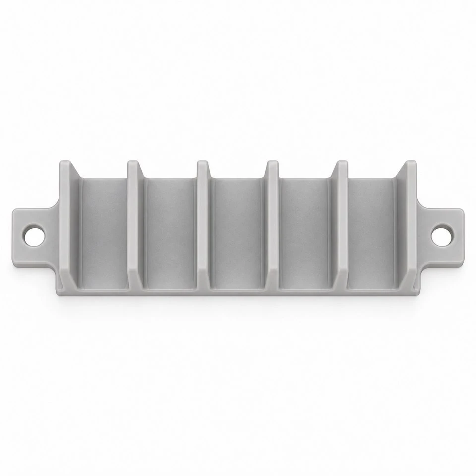
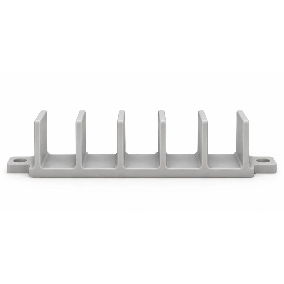
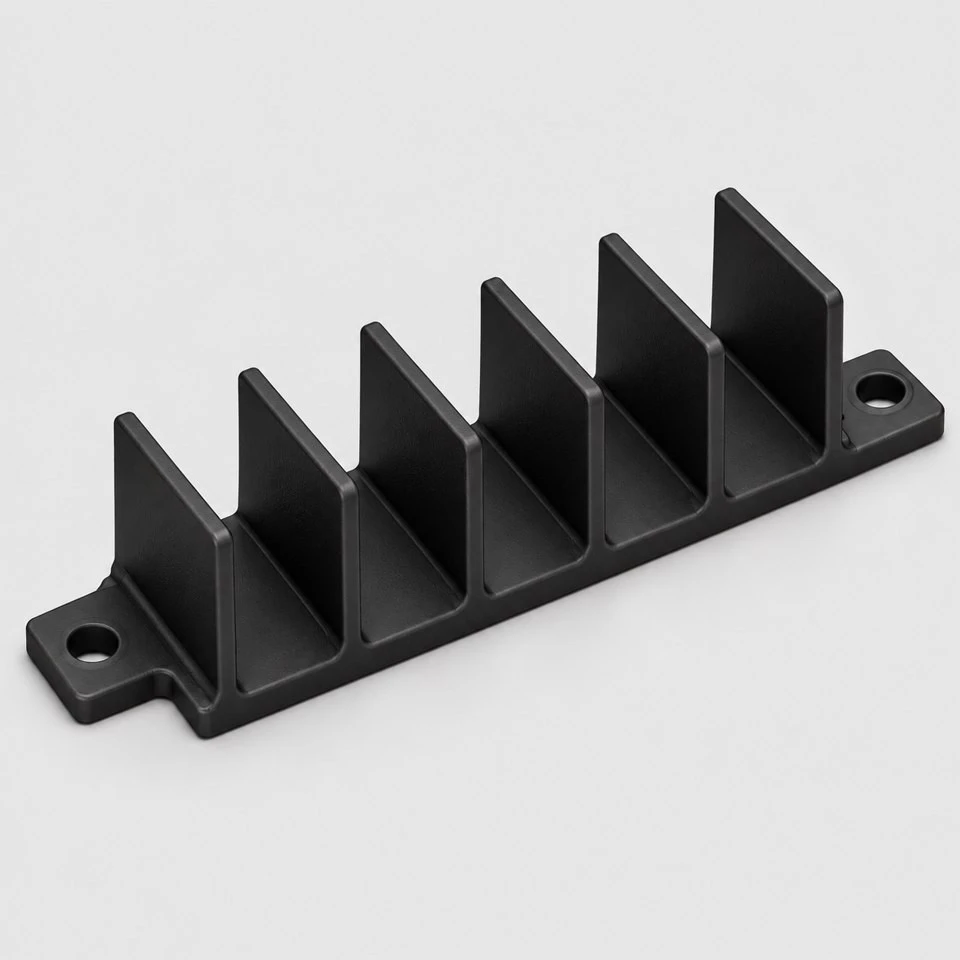
This listing concerns the custom plastic structure, not a complete terminal block. Conductive contacts, screws, cable lugs and protection devices are separate elements unless included in an agreed project scope. The illustrations show an open partition form to explain the molding concept. They do not establish an electrical rating, a protective enclosure classification or compliance of the customer's equipment. Those decisions depend on the approved resin, dimensions, installation and applicable product requirements.
How is the partition pitch established?
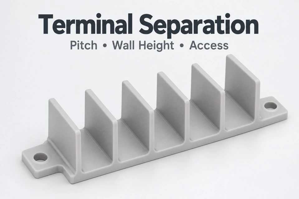
Start from the real terminal centers and the largest installed connection hardware. The useful space between walls must accommodate the lug, conductor insulation and any screw movement. Terminal center spacing and clear compartment width are different dimensions because each partition consumes part of the pitch. State both on the drawing where necessary. A repeated pattern that looks evenly spaced in a model may still restrict the widest cable lug used in production.
Include all approved conductor sizes rather than checking only the smallest demonstration wire. Crimp barrels, insulation sleeves and bend positions can occupy different envelopes even when the screw size is unchanged. If several connection configurations share the same enclosure, overlay their occupied volumes before fixing the barrier shape. This helps identify whether every position can use an identical wall or whether a local relief is needed for a particular end connection.
Which access spaces should remain open for assembly?
A screwdriver approaches the terminal along a defined direction, but an operator's hand and the wire enter from somewhere else. Check those movements independently. Tall walls can obstruct an angled driver or hide the screw head, while a short wall may not provide the intended physical division. The correct height follows the installation sequence and assigned function. A simple tool-access envelope is often more informative than judging the wall height from a finished product picture.
Also review how the operator verifies a completed connection. If a wall blocks the view of the lug seating face, inspection may become difficult. A carefully located window or shortened end wall can improve visibility, but removing material may affect another design requirement. Such changes should be assessed by the customer's equipment designer. The molding review can address how a proposed opening is formed without assuming that easier access automatically satisfies the electrical design.
Why must clearance and creepage requirements be supplied?
Physical distance through air and distance along an insulating surface are separate considerations. Adding a wall changes the geometry, but does not automatically establish an acceptable insulation system. Required distances depend on the equipment design and the conditions under which it operates. We ask the customer to identify the relevant requirements and critical measurement paths rather than assigning a universal spacing to every nylon separator. The drawing should show which surfaces and edges matter.
Slots, fastener holes and nearby metal can alter the intended path. A mounting ear placed close to a conductive screw may create a different situation from the same ear attached with a remote support. Dust, moisture and accessible surfaces also belong to the complete assessment. Where a barrier forms part of an electrical safety function, material approval and equipment testing need to follow the applicable specification. The illustrated shape alone is not evidence of that approval.
What information is needed to select a nylon grade?
PA6 and PA66 describe material families, not one interchangeable performance specification. Resin formulations differ in reinforcement, flame-retardant packages, colorants and other properties. If a particular grade is required, provide the full designation and any permitted alternatives. A request for black nylon or flame-retardant plastic is not sufficiently precise to confirm a material approval. The selected grade should be linked to the intended application and the documentation the buyer needs.
Moisture conditioning also deserves attention when fit is important. A newly molded nylon part and a part that has equilibrated in service may not have identical dimensions or stiffness. Define the state in which critical measurements and assembly checks will be made. Storage, drying and environmental exposure should be considered together. This is especially useful for long partition bases where a small dimensional change can affect several terminal positions at once.
How should the barrier attach to the equipment?
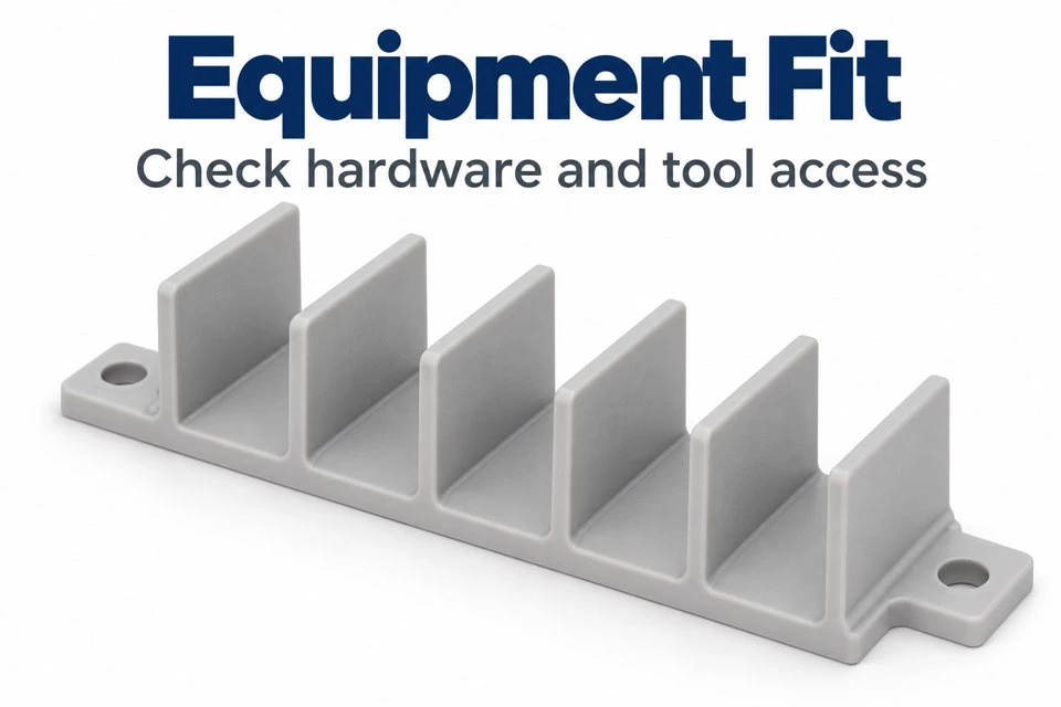
A base with mounting ears can establish the location without placing fasteners inside every compartment. The supporting surface must still be defined. If the base spans an uneven sheet-metal surface, tightening the screws can bend it and shift the walls. Show the seating pads, locating references and the order of assembly. A round locating hole paired with another allowance for length variation may be considered where the equipment design permits it.
Fastener heads, washers and compression limiters need their own space. A metal sleeve or insert changes both the molding arrangement and the nearby interface, so it should be included in the model rather than mentioned only at purchasing. Snap attachments are another possible approach, but they require the mating thickness and installation direction. Retention force, removal access and the expected number of service operations should be agreed before a fastening concept is selected.
What wall features influence molding consistency?
Long thin partitions should be reviewed for filling, release and handling. The polymer must reach the wall ends, while the molded part must withdraw without being scraped or excessively bent. Draft helps release the surfaces, but it also means that compartment width can vary over the height. Specify the measurement height for a critical width. Otherwise, two inspectors can obtain different readings from the same correctly tapered compartment.
The connection between each wall and the base is another important detail. A thick intersection can cool differently from the surrounding material, while a sharp junction can create an unfavorable local stress concentration. Radii and supporting ribs may help when they fit the available envelope. Their positions must remain compatible with terminal hardware and cleaning access. Gate location and ejector contact are reviewed alongside these features so that functional edges are not unintentionally obstructed.
How can handling damage be reduced?
A partition can survive normal installation yet be damaged when parts are stacked loosely in a carton. Upright walls create exposed edges that can catch on neighboring parts. Review whether the components should nest, remain separated or be placed in a defined orientation. If nesting is intended, provide a stop that prevents the walls from being forced together too far. Packaging design should follow the shape instead of assuming that every small molding can be bulk packed safely.
Assembly workers also need a natural place to grip the component. Holding the tallest wall while pressing the base into position can load the wall unnecessarily. Access around a mounting ear or an external handling feature may make the installation more controlled. Such details can be checked with trial parts in the real enclosure. The objective is a practical assembly motion with clear seating feedback, not an unsupported claim that the part cannot break.
What should a dimensional inspection cover?
The inspection plan should connect each measurement to a functional interface. Typical items include the mounting-hole pattern, base seating condition, partition pitch, wall height and the clear width at a specified level. Wall lean may matter more than a small variation in an outside cosmetic edge. Identify the datums used to locate the part in the enclosure, then measure the critical pattern from those datums rather than relying only on accumulated individual gaps.
A representative fixture can complement a dimensional report by showing whether the barrier seats around the terminal arrangement. Include the largest approved lugs and the tools used on the assembly line. Check end positions as well as the center compartments, since nearby enclosure features may restrict the ends differently. Any electrical or flammability testing required for the application must be separately defined and supported by the agreed material and product verification process.
Which project details should accompany a quotation request?
Supply the separator model, a dimensioned drawing and the mating terminal layout. Mark fixed dimensions, allowable changes and surfaces that require special attention. Include the preferred nylon grade, color, trial quantity and expected production quantities. Explain the operating environment, service access and whether the component has an assigned insulation function. A short description of the assembly sequence helps establish why a particular wall, opening or mounting ear is necessary.
If you are replacing an existing component, describe the reason: difficult wiring access, broken partitions, poor fit or a revised terminal arrangement require different responses. Photos of the installed barrier can reveal constraints that are absent from the loose sample. Tooling and sample approval can then be scoped around a clearly identified design revision. Contact amanda@tjswks.com with drawings, material specifications and quantities to discuss a custom nylon terminal separator for your equipment.
Hot Tags: custom nylon terminal separator barriers, China, suppliers, manufacturers, factory, bulk, cheap, low price, quotation, flanged sleeve bearing, high pressure flanged nylon bushings, nylon molded for cover applications, nylon molded for renewable applications, Nylon Strap Oil Filter Wrench, shoulder nylon washer


