


Tianjin SWKS Technology & Development Co.,Ltd is one of the most reliable manufacturers and suppliers of custom nylon robot gripper fingers in China. If you're going to buy bulk cheap custom nylon robot gripper fingers, welcome to get quotation from our factory. Quality products and low price are available.
Custom Nylon Robot Gripper Fingers
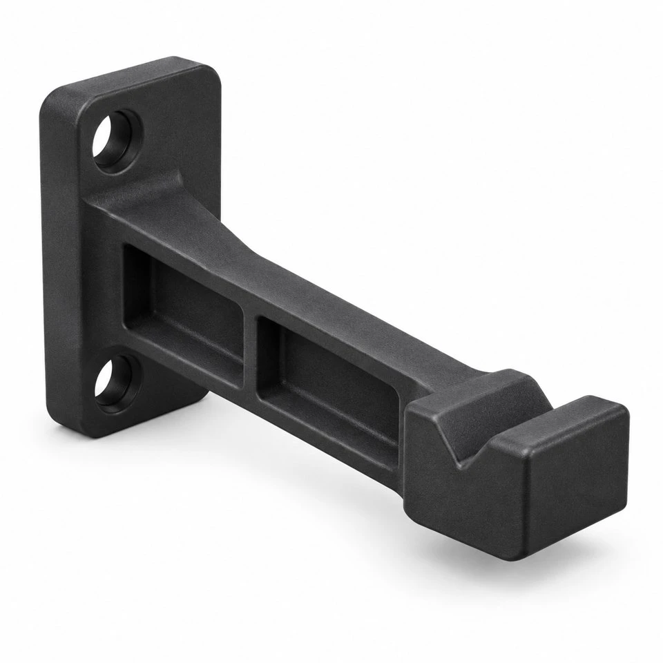
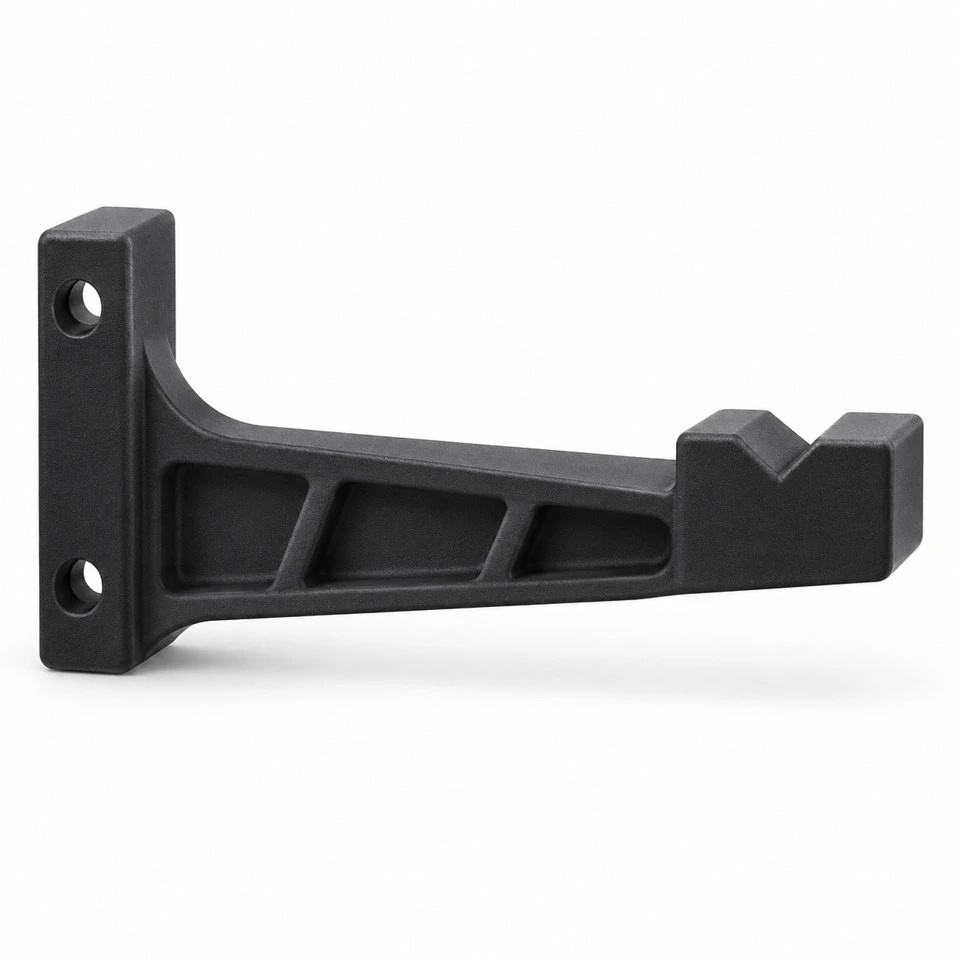
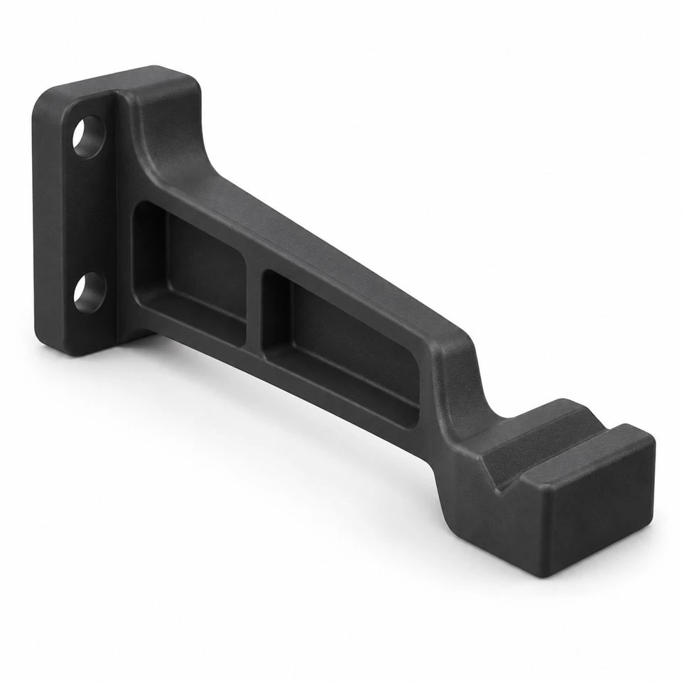
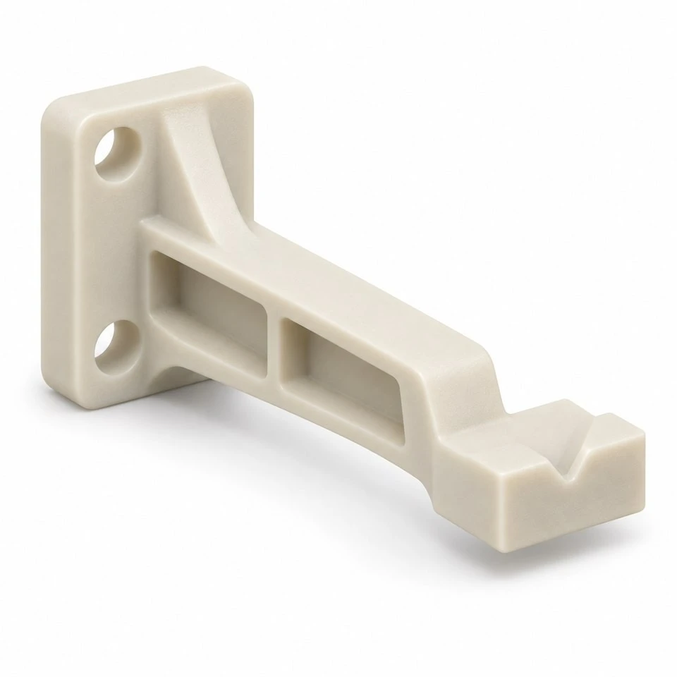
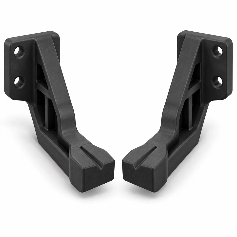
The standard jaws on a parallel gripper rarely describe the shape of the part being handled. A custom finger bridges that gap: one end attaches to the gripper, while the other presents a contact surface developed for the workpiece. SWKS supplies injection molded nylon robot gripper fingers made to an agreed component drawing. The concept shown combines a mounting heel, a supported arm and a shaped contact tip. Send the workpiece model, gripper interface and quantities to amanda@tjswks.com to discuss the plastic finger geometry before production tooling is defined.
Material: ABS/POM/PA66/PP/PC/PA/PU/TPE/TPU etc.
Processing Service: Injection
Drawing: STP/STEP/IGS
Contact: amanda@tjswks.com / 0086-15222707659
What must the finger hold, and where may it touch?
Provide the actual workpiece outline with the permitted contact regions marked. A cylindrical component may offer a broad gripping area, while a molded housing may allow contact only along a narrow reinforced edge. Cosmetic faces, delicate features and assembly openings should be identified early. The finger should follow those restrictions rather than simply matching the most visible surface in a photograph. Include the variation between acceptable workpieces, because the largest and smallest parts may meet the finger differently.
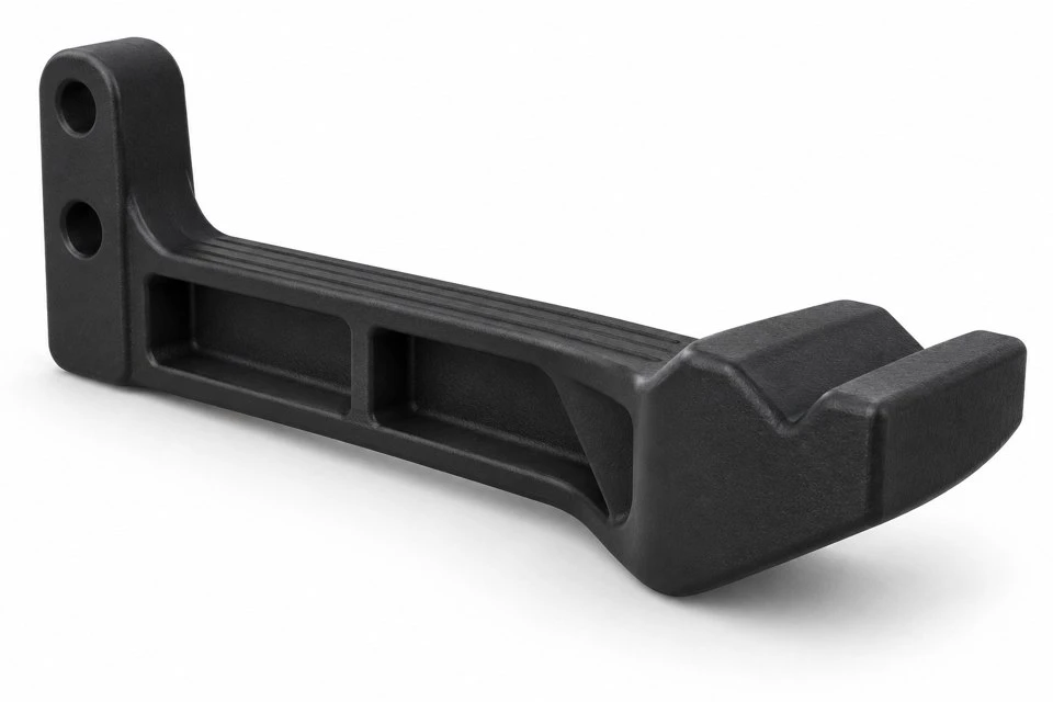
Explain how the workpiece is supported before pickup and after placement. A finger that can hold a loose sample may be unable to reach it inside a tray pocket or beside a fixture stop. Show neighboring parts and the approach direction in the model. The illustrated finger is a custom plastic component concept; the gripper actuator, robot, sensors and workpiece are outside its supply scope unless specifically included. No gripping force, payload or cycle-life rating is assigned to the rendering.
How does the contact shape affect pickup and release?
A shallow V profile can locate a cylindrical shape between opposing fingers, but the angle and depth must suit the workpiece and movement. A deep pocket may retain a component after the jaws open, particularly if it is tilted during placement. A broad flat pad presents another contact arrangement and may require different positioning control. Mark the intended contact points on an assembly section and check them through the complete pickup and release sequence, including the allowed part variation.
Specify whether minor surface marks are acceptable and how they will be judged. Nylon should not automatically be described as non-marking for every finish. Surface texture, embedded debris, contact pressure and relative movement all matter to the application. Where a separate contact pad is required, define its attachment and replacement method. Do not assume that adding a soft material solves a location problem; the assembled contact profile still needs to hold and release the workpiece as intended.
Which positions define the required jaw travel?
Show the fully open position, the expected gripping position and the available mechanical travel. The gap between two loose fingers on a bench does not establish whether a particular actuator can use them. Include the gripper's mounting faces and any adapter plates. A long finger or inward offset tip can change the space available near the jaw body. The supplier needs the assembled positions to review the component envelope, while the equipment designer establishes the required actuation and gripping conditions.
Also examine the release clearance around the largest workpiece. Opening sufficiently to stop applying force may not create enough space for the finger to withdraw without contact. Tray walls, locating pins and adjacent products can restrict that withdrawal. Include the robot approach and retreat directions where they control the finger shape. The final geometry should serve the complete handling motion, rather than only the static image of a part held between two symmetrical tips.
Where do the mounting references sit on the gripper?
Supply the jaw interface drawing with hole spacing, seating surfaces and locating features. Two clearance holes can retain a finger without precisely locating its contact tip. If a dowel, shoulder or fitted edge establishes position, show it on both the finger and the mating assembly. State which reference is used to set the distance between opposing contact surfaces. This avoids applying tight dimensions to a tip while leaving its position dependent on an undefined mounting adjustment.
Fastener access needs to remain available when both fingers are installed. Show the screw heads, driver approach and any washers or inserts included in the arrangement. The mounting heel should have adequate support under the intended tightening method. Repeated replacement may call for a different interface from a finger fitted once during equipment assembly. Identify whether left and right components are identical or mirrored so that the drawings, mold proposal and packing quantities can be kept unambiguous.
What loads should be considered along the finger arm?
Describe the forces and movements expected during the handling cycle. Closing on a stationary part, accelerating a held component and touching a fixture during an abnormal movement are different conditions. State the allowed operating envelope and the loads used by the equipment designer. A narrow arm with a large offset tip deserves review around its root and mounting heel. The plastic component should be assessed against the actual load path, rather than selected from workpiece mass alone.
Stiffness can matter as much as the absence of visible damage. If the tips deflect, the workpiece position may change during transfer or placement. Define the acceptable displacement and its measurement condition where this controls the application. Reinforcing ribs and generous transitions may form part of the proposed geometry, but their presence is not a substitute for evaluation. The completed gripper assembly needs suitable validation under the intended loads, speeds and actuator settings.
Which nylon grade and conditioning requirements belong on the drawing?
Specify PA6 or PA66 and the complete grade designation when a material is already approved. State whether reinforcement or other modification is required or permitted. These are purchasing requirements, not details to infer from a black or natural-colored sample. Include operating temperature, cleaning agents and exposure to oils or other substances around the cell. The material proposal should address the real handling environment, including storage and maintenance conditions that differ from normal operation.
Nylon's moisture condition is also relevant when establishing dimensions and stiffness requirements. Agree how samples are conditioned and when measurements are taken. A dry component and one exposed to the plant environment should not be compared without acknowledging their condition. Where a controlled state is necessary, include it in the inspection and packaging instructions. Any food-contact, flame, electrostatic or other compliance requirement must be tied to an appropriate specified grade and documentation rather than the general nylon material family.
How can an offset finger remain practical to injection mold?
Review the arm, heel and contact tip together when considering mold opening direction. Through-holes, open relief pockets and contact grooves need to be oriented for an agreed tooling concept. An enclosed sideways feature or a retaining hook can introduce additional tooling questions. Explain why such a feature is needed before freezing its shape. A modest change to a mounting detail can be worthwhile if it preserves the function while simplifying release from the mold.
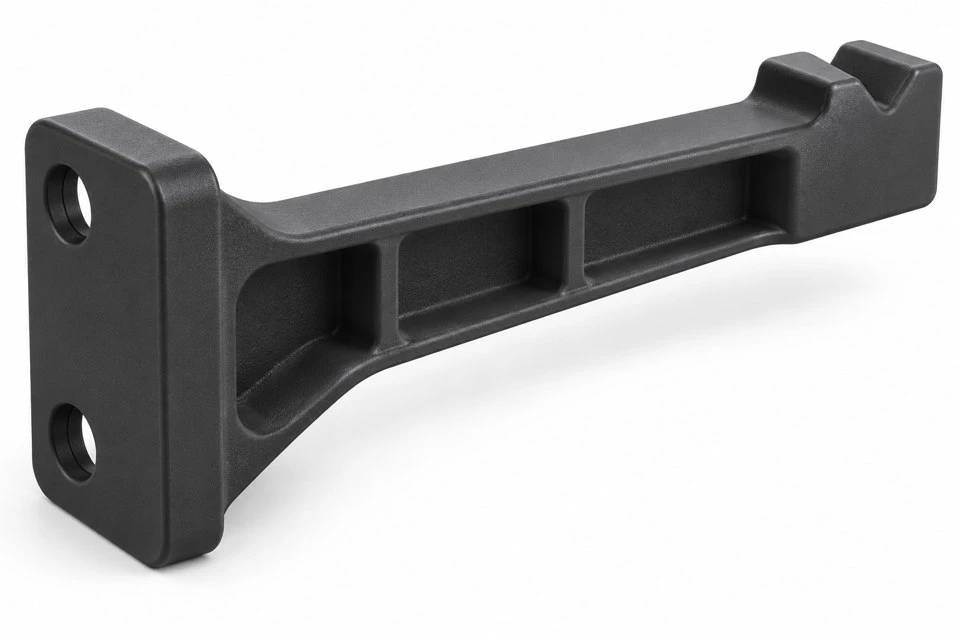
A thick solid arm is not the only way to support the tip. Cored regions and ribs can form a supported section, subject to the mechanical requirements. Avoid abrupt thickness changes where the mounting heel meets the arm. Draft on a contact groove or seating face must be considered at the functional measurement location. Gate and ejector positions should be agreed so raised remnants do not interfere with the gripper mounting face or the workpiece contact area.
Does the contact profile require a finishing operation?
Some projects may use an as-molded contact shape, while others require selected surfaces to be finished after molding. Identify which dimensions control workpiece location and which simply provide clearance. The manufacturing proposal should distinguish those surfaces. If a fine adjustment is planned during commissioning, describe how it will be made and which references must remain available. A general request for precision everywhere does not tell the supplier how the finger will locate the workpiece.
Define acceptable flash and surface condition around the contact edges. A small projection in an unused relief pocket may be harmless, while a similar feature on the V profile can change where the workpiece rests. Inspection should reflect that difference. Where contact surfaces are finished, agree the process and resulting texture with the sample approval. Changes to the finishing method should be reviewed against the same workpiece and inspection criteria used for the original approval.
What should be checked before the robot cell runs unattended?
Fit samples to representative production gripper jaws and use workpieces covering the agreed dimensional range. Check approach, closing, transfer, placement and retreat. Confirm that the fingers do not contact the tray or fixture in any permitted position. If the application has force, deflection, slip or service-cycle acceptance limits, agree the test conditions before trials. A successful pickup of one sample is useful development evidence, but it does not establish the complete operating envelope.
Record the component revision, resin grade, conditioning state and actuator settings used during approval. Include the maintenance and replacement process where repeat positioning matters. Workpiece damage, debris accumulation and changes to the contact surface should be assessed according to the equipment's inspection plan. If a tip geometry is adjusted after a trial, review the travel clearance and mounting relationships again. The production component should remain linked to a clearly identified approved configuration.
What should a custom gripper finger quotation request include?
Send the finger and workpiece models in STP, STEP or IGS format where available, together with the gripper mounting drawing. Mark contact regions, restricted areas, important tolerances and the available opening stroke. State the nylon grade, color, trial quantity and expected batch quantities. Identify whether a mirrored pair is needed and whether inserts, pads or secondary finishing form part of the supply. Tooling and component costs can then be reviewed against a consistent scope.
For a replacement finger, photographs of the installed assembly and a description of the actual difficulty help focus the review. Loose positioning, difficult release and a cracked mounting heel point to different interfaces. Keep the supplied drawing revision aligned with the fixture and workpiece used for testing. Contact amanda@tjswks.com with drawings, material requirements and quantities to discuss custom injection molded nylon robot gripper fingers for your automation equipment.
Hot Tags: custom nylon robot gripper fingers, China, suppliers, manufacturers, factory, bulk, cheap, low price, quotation, custom molded nylon for gas handling applications, custom molded nylon for wire routing applications, nylon molded for pressure applications, nylon molded for tight tolerances, nylon plumbing parts, Nylon Reinforced Plastic Machine Parts


