


Tianjin SWKS Technology & Development Co.,Ltd is one of the most reliable manufacturers and suppliers of custom pa66 nylon clevis linkage ends in China. If you're going to buy bulk cheap custom pa66 nylon clevis linkage ends, welcome to get quotation from our factory. Quality products and low price are available.
Custom PA66 Nylon Clevis Linkage Ends
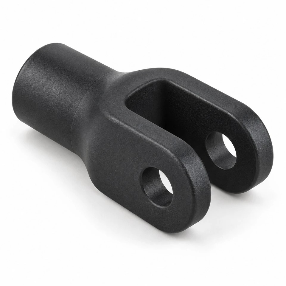
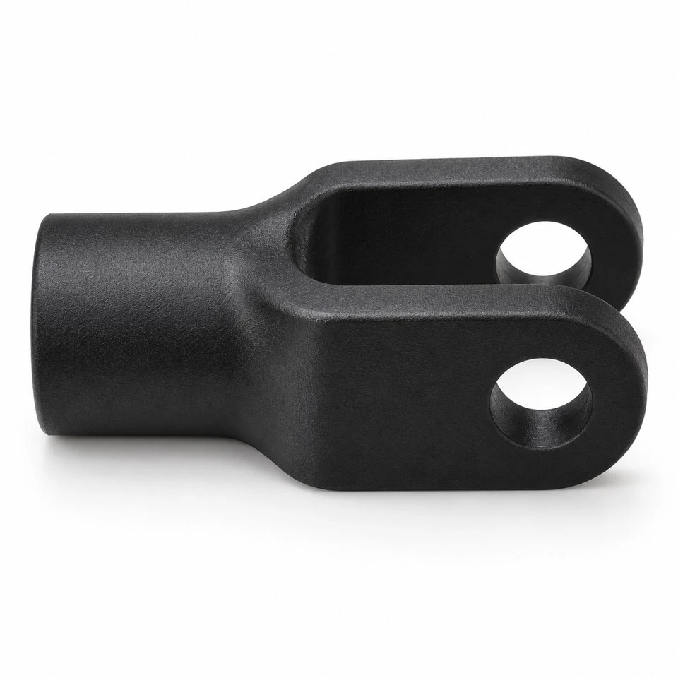
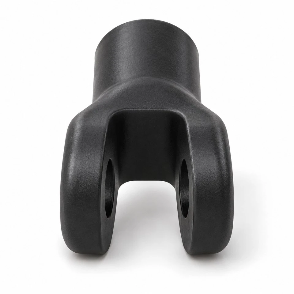
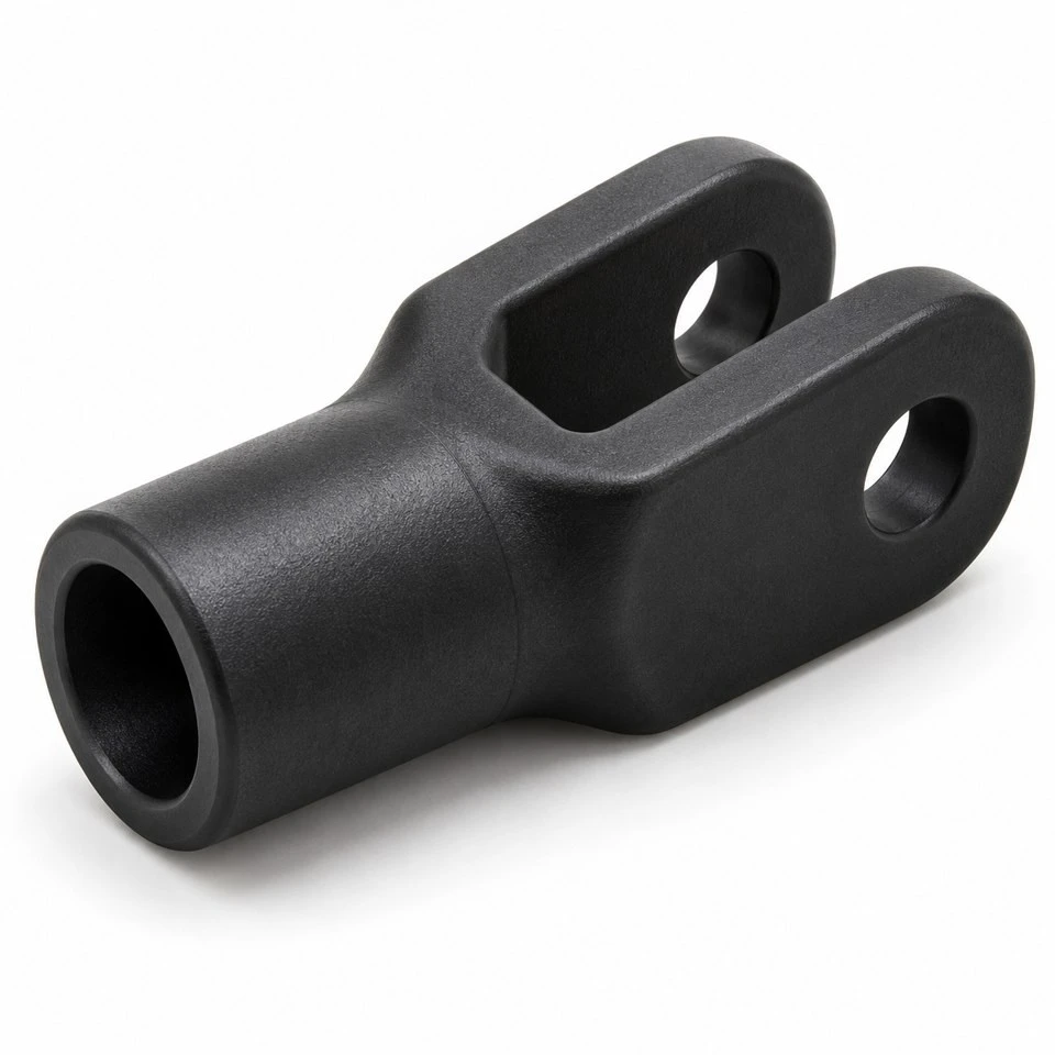
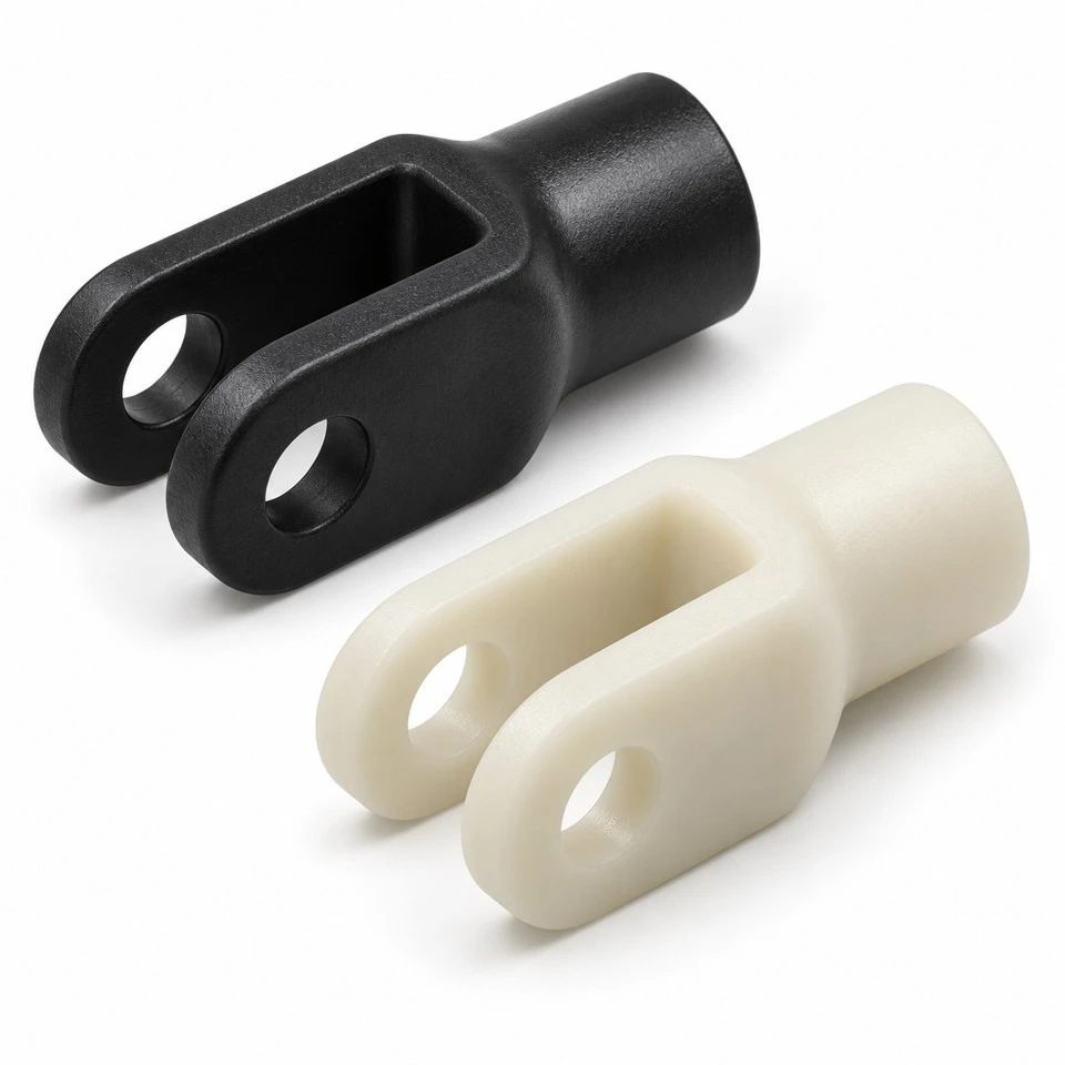
A forked connection can link a rod to a pivoting tongue within a compact industrial mechanism. SWKS develops custom injection molded PA66 nylon clevis linkage ends around the required pin axis, fork clearance and rod interface. The illustrated concept uses two rounded cheeks with aligned transverse holes and a cylindrical shank with a plain rear socket. Final geometry follows the customer assembly. Send your drawing and quantity requirements to amanda@tjswks.com for quotation.
Material: ABS/POM/PA66/PP/PC/PA/PU/TPE/TPU etc.
Processing Service: Injection
Drawing: STP/STEP/IGS
Contact: amanda@tjswks.com / 0086-15222707659
What does a molded clevis do in a linkage?
A clevis provides two spaced cheeks that receive a mating tongue between them. A transverse pin passes through the aligned holes and the mating component to create the intended pivot connection. The shank joins the fork end to the rest of the linkage. The illustrated nylon concept combines that fork geometry with a cylindrical shank and a plain rear socket, with the final connection method defined by the customer assembly.
The clevis shape alone does not define a complete joint. The pin, retention hardware, mating tongue and rod interface all affect its operation. State whether the joint moves through an angle during service or mainly accommodates installation alignment. Those duties may require different clearances and validation. The concept images show a custom plastic component, not a complete qualified linkage assembly or a replacement approved for a named machine.
Which mating tongue dimensions determine the fork gap?
Provide the width, thickness and hole details of the tongue that enters the fork. The internal gap should accommodate the intended movement and the variation of the mating component. Excessive lateral clearance may introduce unwanted play, while insufficient space can cause rubbing or prevent assembly. Show any washers or spacers that occupy the gap so their thickness is included in the interface review.
Also identify how far the tongue enters the fork and the clearance it needs near the root during rotation. A tongue can fit between the parallel cheeks at rest yet interfere with the curved root as it moves. An assembly section at the travel limits helps define the required envelope. The final gap, cheek length and root profile should be reviewed together rather than set from tongue thickness alone.
How are the transverse pin holes specified?
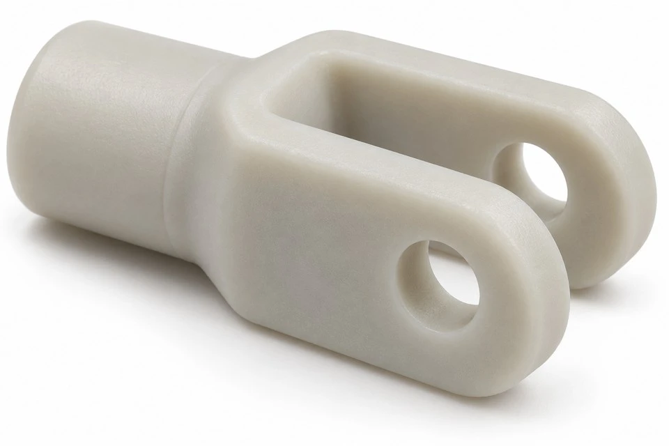
Show the required pin diameter, hole size, hole location and relationship between the two cheeks. The holes must align sufficiently for the defined assembly method, and their position relative to the shank establishes the linkage geometry. Two independent diameter measurements do not fully describe this relationship. Identify the drawing datums and the inspection approach used to check the pin axis across the fork.
State whether the pin rotates in the nylon holes, is retained in one component or uses a separate bearing interface. Include pin material, surface finish and dimensional variation. A clearance intended for a moving pin differs from a connection that is fixed after assembly. If repeated movement or wear matters, define the operating conditions and acceptance criteria. The appearance of an aligned pair of holes cannot establish the service life of the joint.
What keeps the pin in place during operation?
Provide the intended pin retention arrangement, including clips, headed features, washers or other hardware. The illustrated component has plain holes and does not include a retaining pin. Make clear which items are supplied with the molded part and which are assembled by the buyer. A quotation for the nylon clevis should not be assumed to include an unspecified hardware kit or an independently designed locking system.
Review the space needed to install and remove the retainer in the actual machine. A nearby wall can obstruct access even when the joint fits dimensionally. If maintenance requires repeated disassembly, describe the procedure and the parts that are replaced each time. Any retention test should use the specified hardware and assembly orientation. Keep the pin retention requirement separate from the mechanical fit of the pin within the fork holes.
How does the rear socket connect to a rod?
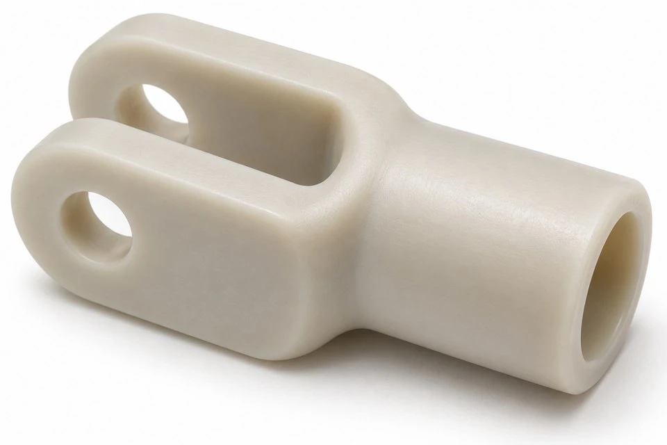
The concept shows a plain axial socket at the rear of the cylindrical shank. Supply the mating rod drawing and the intended retention method. A plain socket does not imply an internal thread, adhesive connection or interference fit. If the final design needs a threaded insert, cross pin or another feature, identify it explicitly so the component model and quotation include the appropriate interface and manufacturing steps.
Define the insertion depth and the axial location of the rod relative to the pivot pin. These dimensions affect the effective linkage length. State whether adjustment is required after assembly and how the selected position is secured. Where a metal insert is proposed, include its geometry and installation requirement. The shank wall and transition into the fork need to be reviewed against the chosen rod connection rather than retained unchanged by assumption.
Which loads should be considered at the fork root?
Provide the force direction and magnitude, operating cycle and any relevant loading at the travel limits. A clevis intended to transmit an axial force can also experience bending if the assembly is misaligned. Show the complete linkage and the expected movement so the review can distinguish the intended force path from side loads. Include installation loads or defined abnormal conditions where the equipment specification requires them.
The root radius, cheek thickness and material around the pin holes all influence the component response. A thicker cheek alone does not establish a higher qualified capacity if the root or rear connection remains limiting. Do not assign a universal load rating from a catalog visualization. The buyer's engineering requirements and sample validation should determine acceptance for the actual assembly, with the approved drawing and resin grade recorded together.
How much angular movement should the joint permit?
Specify the working angular range and the locations of nearby rods, brackets and covers. The mating tongue must clear the fork root, and the surrounding assembly must clear the outside of the cheeks. A model at only one neutral position may conceal interference at the end of travel. Provide the relevant extreme positions so the required space can be checked before the mold design is finalized.
If the joint is intended to pivot primarily in one plane, explain how the assembly controls out-of-plane movement. A simple clevis should not be assumed to behave as a spherical joint. Where misalignment is unavoidable, the overall connection may need another design feature. Discuss that requirement during drawing review. Functional approval should reproduce the intended angular movement with the actual mating parts, rather than rely on free movement of an empty fork.
When is PA66 an appropriate material candidate?
PA66 can be considered where the selected grade provides the required behavior for the linkage environment. State the approved resin designation where available. Otherwise provide temperature, chemical contact, cleaning exposure and mechanical duty for material review. Unfilled and reinforced grades can differ in stiffness and behavior at local contact areas. A grade should therefore be selected for the complete interface rather than simply for the feel of a rigid sample.
Nylon moisture condition is relevant when fit and mechanical response are important. Agree the condition used for dimensional inspection and functional testing, and describe the environment in which the component is stored and operated. A comparison between differently conditioned samples may obscure the reason for a fit difference. Black and natural-colored views illustrate appearance options; they do not independently establish a material grade, reinforcement level or performance classification.
What molding details affect the pin and socket interfaces?
The transverse pin holes and rear axial socket require a coordinated tooling approach. Core directions, parting locations and any necessary tool actions should be reviewed against the final geometry. Do not assume a particular simple mold configuration before those features are assessed. The open fork and shank transition also require attention to filling and cooling, especially where wall thickness changes or material flow divides around a core.
Mark functional regions where a gate vestige, parting flash or ejector mark would interfere with assembly. These may include the pin holes, inner cheek faces and rod seating surfaces. Specify acceptable edge treatment at the hole entrances and tips. Any secondary operation needed to meet a defined interface should be agreed in the supply scope. Controlled finishing should preserve the dimensions established on the released drawing.
How should initial samples be inspected and tested?
An inspection plan may cover fork gap, cheek thickness, pin-hole size and alignment, socket size and depth, and the distance from the rod reference to the pivot axis. Choose datums and fixtures that represent the intended location without forcing the part into shape. Record material identity, drawing revision and sample condition. Visual checks should include filling, flash and unwanted sharp edges at the handling and mating surfaces.
Functional evaluation should use representative rods, tongues, pins and retainers. Check assembly, the agreed motion range and retention before applying the specified duty test. Define forces, cycles and acceptance criteria in advance so results can be compared consistently. If a sample is accepted after a mating part has been modified, update that assembly information. The approved result should remain connected to the interfaces that will actually be used in production.
What information makes a custom clevis quotation clear?
Send an STP, STEP or IGS model and a dimensioned drawing, together with the mating tongue, rod and pin details. Include the force and motion requirements, working environment, pin retention method and intended assembly sequence. State the PA66 grade and color, first order quantity and estimated repeat demand. If development starts from a sample or sketch, identify the features that must remain and the issues the new design should resolve.
Agree whether the supply consists of the molded clevis alone or includes specified inserts or hardware. Use distinct component numbers for similar clevises with different gaps or pivot locations. Packaging should protect the cheeks from distortion and keep the socket and holes free of debris. Define any inspection records and material traceability required. Repeat orders should reference the controlled drawing and the same mating arrangement used for sample approval.
Contact amanda@tjswks.com to discuss a custom PA66 nylon clevis linkage end for your equipment.
Hot Tags: custom pa66 nylon clevis linkage ends, China, suppliers, manufacturers, factory, bulk, cheap, low price, quotation, custom molded nylon for container applications, custom molded nylon for energy efficient applications, custom molded nylon for lid applications, nylon molded for guiding applications, nylon molded for impact resistance applications, nylon molded for sealing applications


