


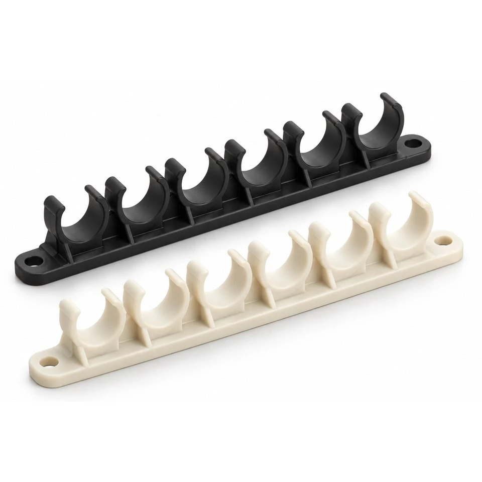
Tianjin SWKS Technology & Development Co.,Ltd is one of the most reliable manufacturers and suppliers of custom pa66 pneumatic tube routing comb bracket in China. If you're going to buy bulk cheap custom pa66 pneumatic tube routing comb bracket, welcome to get quotation from our factory. Quality products and low price are available.
Custom PA66 Pneumatic Tube Routing Comb Bracket
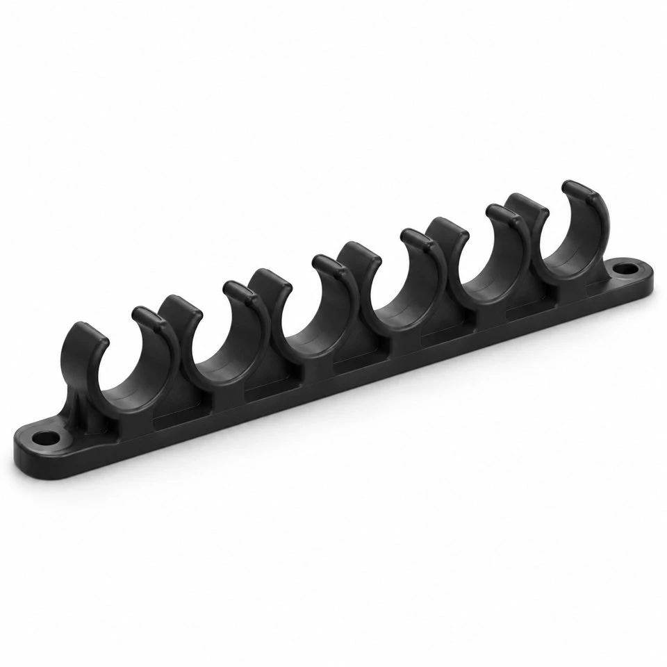
Pneumatic control cabinets and compact assembly stations often route several flexible air lines across the same mounting surface. A custom tube comb gives each line a defined place while keeping the group accessible for inspection and servicing. SWKS offers injection molded PA66 pneumatic tube routing comb brackets developed around the customer's tubing and mounting layout. The illustrated concept combines a continuous backbone, open retaining saddles and two end mounting ears. Send your drawing, tube specifications and required quantities to amanda@tjswks.com for a drawing review and quotation.
Material: ABS/POM/PA66/PP/PC/PA/PU/TPE/TPU etc.
Processing Service: Injection
Drawing: STP/STEP/IGS
Contact: amanda@tjswks.com / 0086-15222707659
What does a tube routing comb do inside a machine?
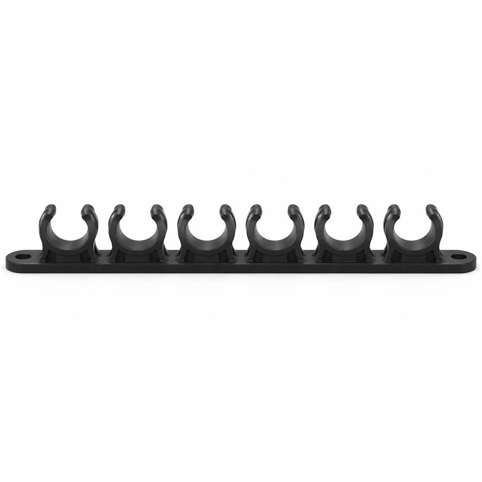
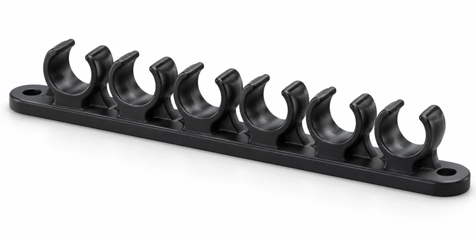
The bracket separates parallel tube runs into individual positions on one mounting backbone. The six-channel concept provides an open seat for each line, rather than enclosing the entire group in a common tie. That arrangement can help a technician follow a line through an assembly and reach one tube without disturbing every neighboring run. The number and spacing of the channels should follow the actual routing requirement, including spare lines or connections that need additional access.
This component organizes the outside of the tubing. It does not form a pressure connection, seal a fluid passage or establish the pressure rating of an air circuit. The images are design visualizations of a custom molded bracket; they do not document a manufactured installation or an approved dimensional drawing. Tubing, fittings, fasteners and machine rails remain separate unless they are expressly included in the supply scope. The finished layout needs to be reviewed with those mating components.
Which tube dimensions determine the retaining channel?
Provide the tubing outside diameter and its allowed variation. The outside diameter defines the interface with the bracket; the tubing bore alone does not. Identify the tube material and construction as well, because two tubes with the same nominal outside size may respond differently when pushed through an opening. For a mixed group of lines, list each required diameter by position. A quotation based on six identical seats should not be assumed to include a redesigned combination of sizes.
Decide whether a channel simply supports the tube or is expected to resist removal. These functions require different acceptance criteria. Excessively tight retention can make installation difficult or compress a soft tube, while a loose seat may let the line lift out during service. Establish insertion, removal and holding requirements with representative tubing. The opening width, internal radius and lip geometry can then be reviewed against that defined interface rather than selected from the nominal diameter alone.
How should the open lips contact flexible tubing?
The retaining lips should have smooth lead-ins and contact edges appropriate to the tube. A narrow sharp edge may catch the outer surface as the tube is installed or removed. Show the intended direction of insertion and the space available above the bracket. A technician should be able to place the line without forcing it around nearby fittings or levering against a neighboring saddle. The layout should also leave room for fingers or the agreed installation tool where one is required.
For tubing that moves relative to the bracket, identify the movement and the expected service cycle. Repeated rubbing at a lip is a different condition from a stationary line resting in a seat. Any abrasion or retention test should use the actual tube formulation and representative movement. Nylon should not be assumed to protect every soft polyurethane or other tube surface under all conditions. Functional acceptance belongs in the project specification and sample approval, together with the required finish of the contact region.
Why does the bend space beside the bracket matter?
A comb can hold the tube positions correctly and still sit too close to a fitting or obstruction. Show the route on both sides of the bracket, including the bends needed to reach each connection. Supply the tubing manufacturer's applicable bend restrictions or the equipment designer's required routing envelope. The bracket should support that route while leaving enough distance for the tube to approach a fitting in the intended direction. A neat row of seats does not by itself establish a suitable installed bend.
Check the outermost lines as well as the central ones. Lines at the ends may need to turn past a mounting ear, enclosure edge or rail. Include the installation sequence if tubes are connected before they enter the comb. A layout that works with loose straight lengths may become awkward when the fittings are already attached. The available routing space, bracket height and channel pitch should therefore be assessed together in the machine assembly.
How are the end ears attached to the support?
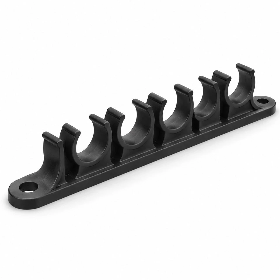
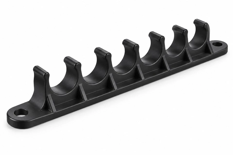
The concept uses a through-hole mounting ear at each end of the backbone. Provide the support surface, fastener size, hole spacing and access direction. If an adapter joins the bracket to a rail, include its drawing rather than describing the comb as universally compatible with that rail. Identify the seating surfaces that keep the base aligned. The holes retain the bracket, while any required locating features should be specified separately.
Review the tightening method for the plastic ears and the support beneath them. An unsupported ear can distort when a screw is tightened, changing the backbone position or stressing the adjacent saddle. Include washers, compression controls or other hardware when the assembly requires them. Do not use the tube comb as a general load-carrying clamp without a separate mechanical review. Its mounting and retention requirements should match its agreed routing function.
When is PA66 an appropriate material candidate?
PA66 can be considered for a routing bracket where the required stiffness, toughness and exposure conditions suit the chosen grade. Specify the complete resin designation if one is already approved. Otherwise provide operating temperature, cleaning agents, workshop oils and other substances that may contact the bracket. Suitability needs to be reviewed for those specific conditions. A generic material name does not identify the additive package or establish compatibility with every pneumatic tube and maintenance chemical.
Unfilled and reinforced grades should be discussed in relation to the design. Reinforcement may change the stiffness of the backbone and the behavior of a flexing retaining lip. A grade should not be substituted only because it makes the part feel more rigid. If the lips must deflect repeatedly, describe that requirement and validate it with samples. State color, any flame requirement and the documentation needed before tooling or repeat production is released.
How should moisture condition be handled during fit approval?
PA66 absorbs moisture, so conditioning is relevant when dimensions and retention behavior are important. Agree the condition in which initial samples will be inspected and tested. Also describe the environment in which the bracket is stored and used. Comparing a dry sample with a component exposed to the factory environment without recording the condition can obscure the reason for a fit difference. The purchasing drawing or quality agreement should identify any controlled conditioning requirement.
The tubing should be considered during the same approval. Tube size, temperature and handling history can influence the observed insertion behavior. Keep a representative approved tube sample or a clearly specified test material for repeat checks. Record how insertion and removal are performed, including the direction and speed where these matter. An operator's impression can help development, but a repeatable method provides a clearer reference when production batches are compared.
Can the comb be produced as one injection molded component?
The supplied concept is intended as one molded part, subject to tooling review. The opening of the saddles, side walls and mounting holes needs to be considered in the selected mold release direction. Retaining lips can create undercut questions, so a straight-pull mold should not be promised before their geometry is assessed. A revised lip, another parting direction or an additional tool action may be appropriate depending on the final retention and dimensional requirements.
Review wall thickness, radiused roots and the connection between each saddle and the backbone. The gussets should support the intended use without creating abrupt thick intersections. Gate position, filling balance and weld-line locations need consideration across the row. Mark tube-contact edges and mounting references where raised gate or ejector marks are unacceptable. The tool layout, cavity count and trimming method should be agreed against the released component drawing.
Which features can be changed for a different machine layout?
Customization can include tube diameters, channel count, pitch, opening shape, backbone height, mounting-hole pattern and support interface. Where some lines need more frequent service, the designer may choose another spacing or a separate routing group. Provide the complete layout when requesting those changes. Increasing the number of seats on the same mounting span can affect the available access and the way the backbone is supported, so the changes should be considered as one assembly.
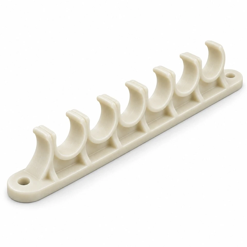
Molded identification features may be useful when the equipment uses fixed line positions. Their size, location and legibility requirements need to be specified, particularly on a small bracket. If the buyer needs a plain part, the production drawing should show that instead. Color variants also need an agreed resin and color specification. The black and natural-colored concept views illustrate options; neither appearance independently assigns a performance classification or certifies the finished installation.
What checks and information support a repeat order?
An agreed quality plan may cover resin identification, complete filling, flash at the lips, channel pitch and width, mounting-hole positions, backbone shape and functional fit with buyer-approved tubing. If repeated insertion and removal matter, define the cycle and acceptance criteria. Check samples on the representative support with the intended fasteners. Packaging should protect the retaining features during shipment and keep the parts free from debris that could transfer to the tube-contact surfaces.
For quotation, send STP, STEP or IGS files or a dimensioned sketch, tube outside diameters and materials, mounting details, working conditions and initial and expected production quantities. Identify the required PA66 grade, color and functional criteria. Keep the drawing revision aligned with the tubing and support used for sample approval. Contact amanda@tjswks.com to discuss a custom PA66 pneumatic tube routing comb bracket for your automation equipment.
Hot Tags: custom pa66 pneumatic tube routing comb bracket, China, suppliers, manufacturers, factory, bulk, cheap, low price, quotation, custom molded nylon for button applications, custom molded nylon for container applications, nylon molded for aesthetic applications, nylon molded for biodegradable applications, nylon molded for connecting applications, nylon molded for plug applications


