


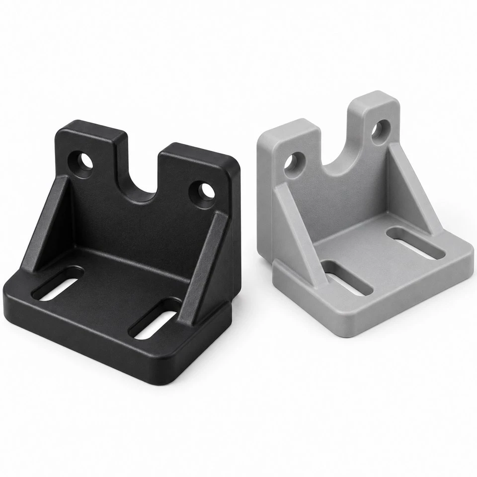
Tianjin SWKS Technology & Development Co.,Ltd is one of the most reliable manufacturers and suppliers of custom injection molded sensor mounting brackets in China. If you're going to buy bulk cheap custom injection molded sensor mounting brackets, welcome to get quotation from our factory. Quality products and low price are available.
Custom Injection Molded Sensor Mounting Brackets
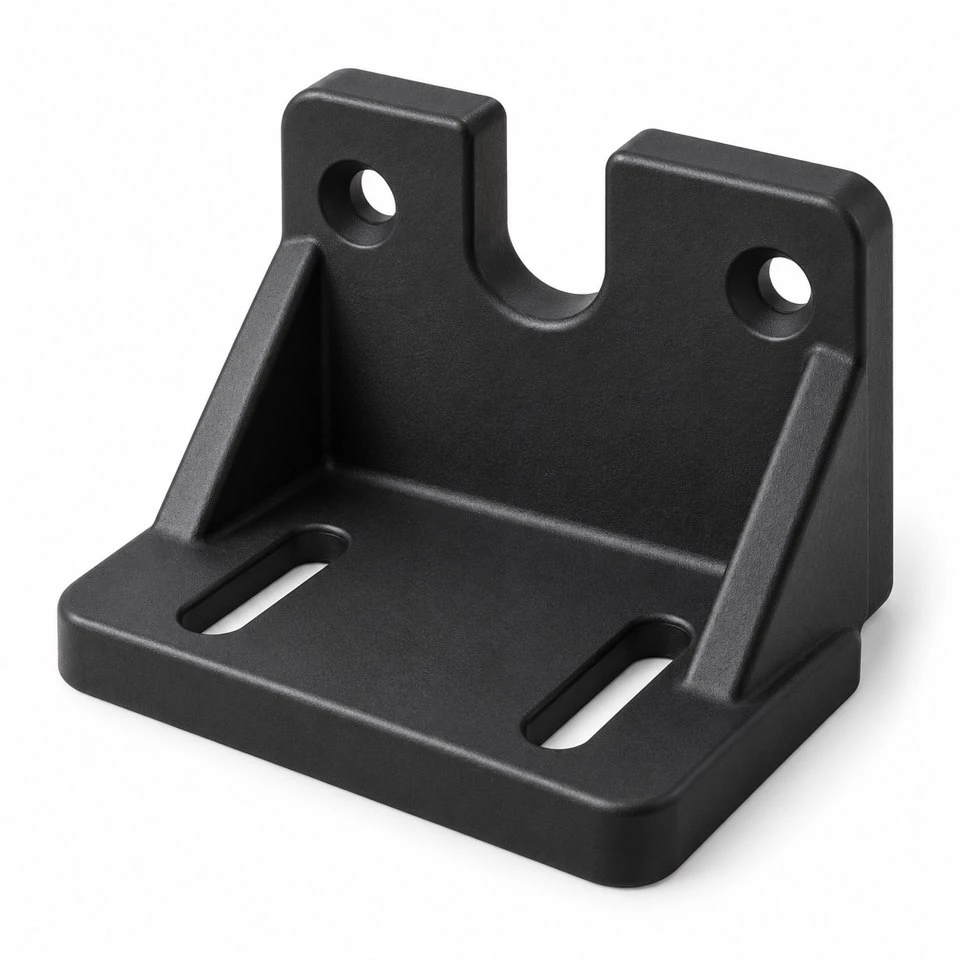
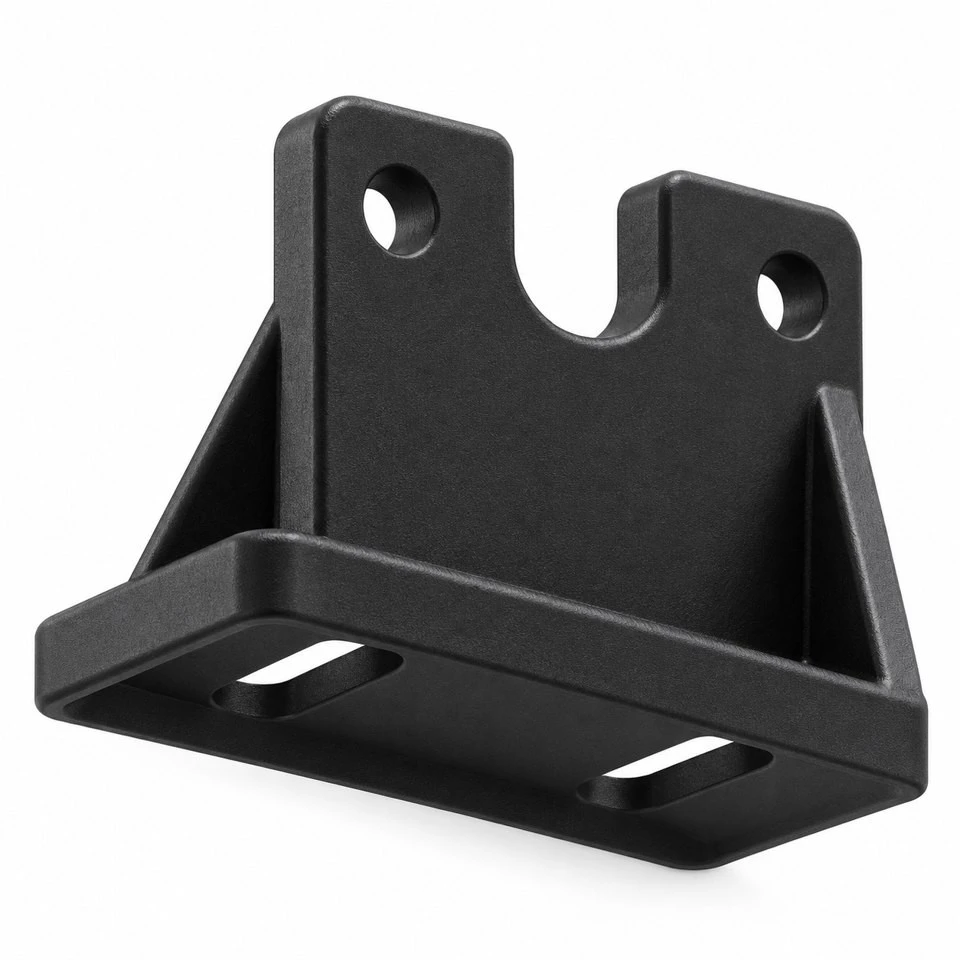
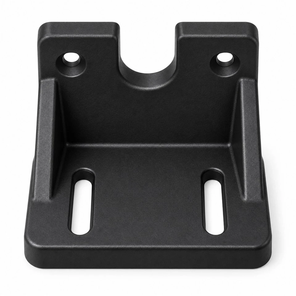
A sensor can be small, yet its mounting interface often determines how easily an electronic assembly is installed, adjusted and serviced. Our custom injection molded sensor mounting brackets are developed around the customer's device and machine interface. The illustrated component uses an L-shaped body, two slotted base fixings, an upright mounting face, side gussets and an open cable clearance notch. It is a custom manufacturing concept for industrial electronics, automation equipment and instrument assemblies, with the final geometry established through approved drawings.
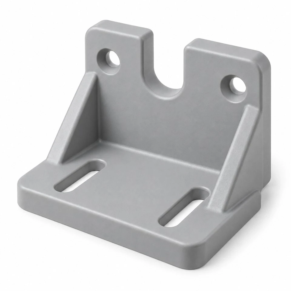
We supply the molded bracket to an agreed specification. The sensor, cable, fasteners and machine frame are separate items unless they are specifically included in the quotation. ABS is one material option for this product family, while other polymers can be reviewed against the operating conditions. The black and light gray images illustrate possible appearances; they do not establish a stocked model, standard size, electrical rating or verified compatibility with any named sensor.
Which installation problems can a custom bracket address?
A standard angle bracket may leave a sensor too close to a neighboring cover, place a connector against a wall or make the adjusting screws difficult to reach. A molded design can combine the mounting face, support geometry and cable clearance within one component. Its value depends on how those features match the assembly. Send the device envelope and the surrounding installation space so the review can focus on the actual obstruction or positioning requirement.
This style can be considered for locating compact sensing devices, supporting instrument modules or attaching small electronic subassemblies inside equipment. Each application needs its own interface definition. A mechanical bracket does not establish sensing accuracy, vibration performance or electrical protection by itself. The complete assembly should be evaluated under the customer's stated conditions before a design is released for production.
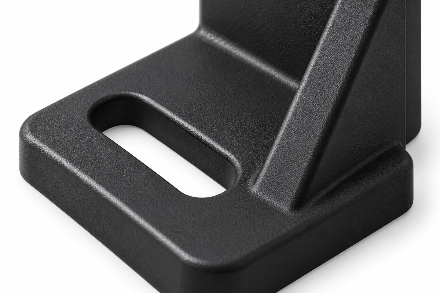
How should the base adjustment slots be defined?
The two illustrated slots allow the designer to consider positional adjustment along the base. Specify their width, overall length, center distance and position relative to the upright face. Also identify the usable adjustment travel after the fastener and washer are installed. The full slot length is not necessarily equal to the available movement in an assembled bracket, particularly when nearby structures restrict access or movement.
Provide the fastener size and head arrangement, along with any washer or compression sleeve requirement. State whether adjustment happens only during initial installation or repeatedly during service. If the bracket must return to a known position, show the separate locating feature or agreed reference method. A slotted fastening arrangement should not be described as a precision locating system without the additional interface and acceptance criteria needed to support that claim.
What needs to be specified on the upright mounting face?
The upright face connects the molded bracket to the device or its carrier. Show the mounting hole pattern, contact area, device orientation and any portion that must remain unobstructed. Two holes are illustrated, but their quantity, position and form can be adapted. If threaded inserts or captive hardware are required, provide their specifications and identify whether they are supplied by the customer or included in the manufacturing scope.
The drawing should distinguish clearance holes from locating holes. When the device needs a defined reference edge, mark that edge and its relationship to the base. Supply a mating model where possible so the available screw engagement and connector clearance can be understood. This is especially useful when the device body extends beyond its fastening points or includes an adjustable sensing head.
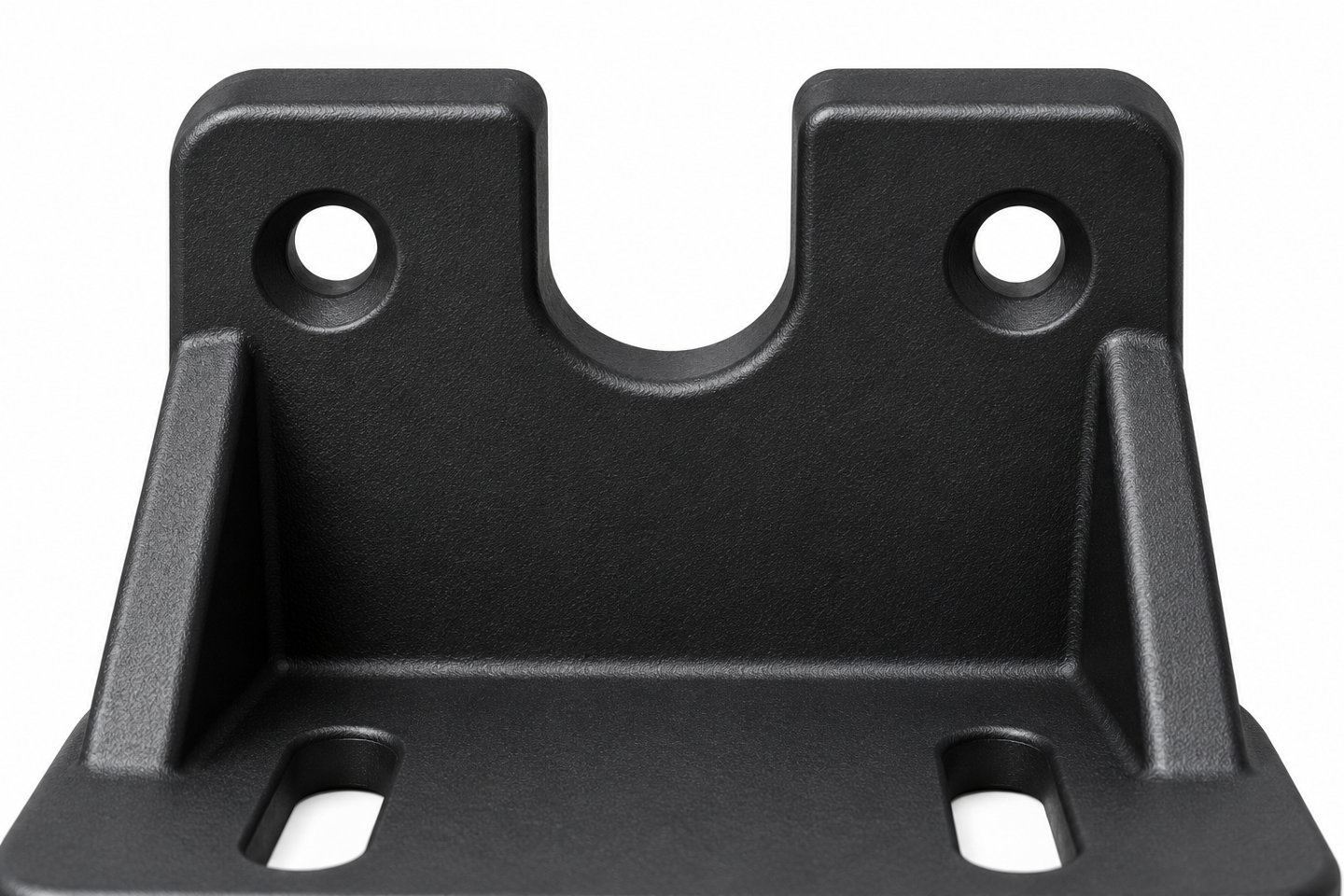
How can the open notch accommodate the cable route?
The open notch at the top of the concept bracket creates a possible route for a cable or connector feature. Its width, depth and edge profile must be matched to the intended assembly. Provide the cable outside diameter, connector envelope and installation direction. A connector may need more clearance during assembly than the cable needs after it has been fitted, so both conditions should be shown.
Tell us whether the cable is free to move or is secured elsewhere. An open clearance notch is not automatically a strain relief, clamp or protective grommet. If controlled cable retention is needed, it should be designed and quoted as a defined feature or separate component. Mark contact-sensitive cable areas and state the required finishing condition at the notch edges, particularly if the cable could move against them during operation.
Why review the gussets together with the surrounding space?
The triangular side gussets connect the base to the upright wall. They are part of the three-dimensional molded structure and must be considered alongside the required access to screws, device surfaces and cable connectors. A larger gusset may obstruct an installation tool even when it fits within the overall machine envelope. Include the tool approach direction or a simple service-access sketch when the assembly is crowded.
Ribs and gussets can provide support without simply making the whole part thicker, but their dimensions still require a molding review. The component's load capability cannot be read from a product image. Identify the forces, contact points and allowable movement relevant to the application. The geometry, material and agreed assembly tests can then be reviewed together instead of assigning a general load limit to every bracket in the product family.
Is ABS suitable, or should another material be considered?
For an ABS plastic injection mold project, we first need the required resin grade and the environment in which the bracket will operate. Color alone does not identify a grade or establish its performance. Provide the expected temperatures, cleaning products, oils and other exposures. Where a material has already been approved by the customer, include its complete designation and any restrictions on alternative grades.
Nylon, POM, PP, PC and other plastics can be considered when the application requires them, subject to a review of geometry and tooling. These materials are not interchangeable simply because the same bracket outline can be drawn in each one. Any change should be recorded in the quotation and approval documents. Flame classification, electrical properties or other special requirements need an exact specification and the appropriate supporting documentation rather than a broad material-family description.
What should be decided before the mold is built?
The part model should identify the functional faces and leave no uncertainty about the current design revision. Manufacturing review then considers how the component can be formed and released from the tool, including the proposed gate, parting features and ejector contact regions. The designer should highlight areas where a molding mark would affect device seating, fastener contact or cable clearance. That information is more useful than a general request for every surface to be perfect.
Appearance requirements should also be tied to the use of the part. An internal bracket may have different cosmetic priorities from an exposed instrument support. State the visible surfaces, texture preference and acceptable color reference. Where a gate remnant or edge condition is important to handling, agree the acceptance method with a drawing note, reference sample or defined inspection criterion before the production approval stage.
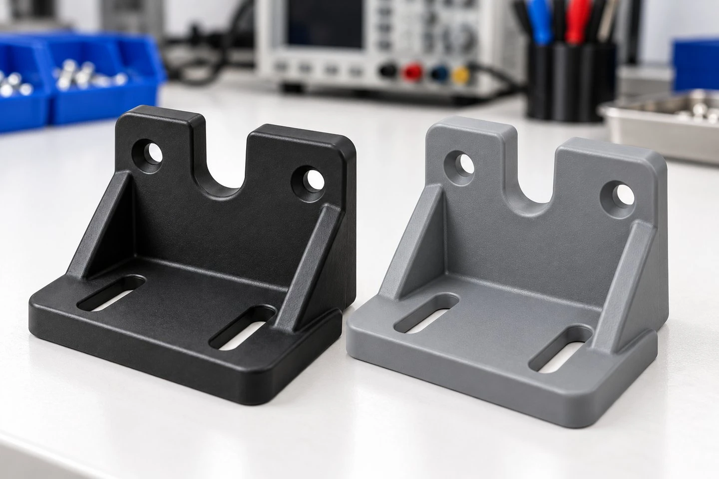
How can first samples be checked in a useful order?
Begin by installing the bracket on its actual support or an agreed fixture. Check that the base seats as intended, the fasteners remain accessible and the slots provide the required adjustment. Next attach the device or its mating gauge and inspect the upright interface. Finally route the cable through the intended assembly sequence and check that neighboring components can still be fitted and removed.
Dimensional inspection should concentrate on the features that control this installation. Examples include slot spacing, the relationship between the base and upright face, mounting hole positions and notch clearance. The drawing should define the applicable tolerances; we do not promise one tolerance for every dimension on every material. If positional stability under operation matters, specify a functional test for the complete mounted assembly and agree the acceptance criteria before reviewing the samples.
Can the bracket include markings or additional assembly features?
A molded part number, orientation arrow or revision identifier can be considered where space permits. Provide the exact artwork and preferred location, keeping identification away from mounting contacts and sensitive clearance areas. Markings should remain readable in the installed orientation if they are intended for service personnel. Any customer logo must be included in the approved manufacturing information rather than added as an informal production instruction.
Additional options might include a locating ledge, an extra cable clearance, a different hole pattern or a provision for separate fastening hardware. Each change should be checked against the whole installation. Specify whether the required delivery is the plastic bracket alone or a subassembly, and list all included items. Packaging can then be agreed to protect the upright wall and mating surfaces during transport and handling.
What information helps us prepare an accurate quotation?
Please send the STP, STEP or IGS model, dimensioned drawing, preferred resin, color and required quantity. Include the sensor or mating-device model when available, along with the mounting support dimensions and cable route. If the existing bracket is causing an installation issue, photographs of the assembled condition are useful, especially when they show tool access and surrounding components. Identify dimensions that are still under development so the quotation assumptions are clear.
We confirm the manufacturing scope, tooling proposal, sample arrangements, minimum order quantity and production schedule for the specific project. Repeat demand and expected design changes also help define a suitable supply plan. This product is offered as a custom molded industrial component, with the released drawing and approved specification controlling production. We welcome inquiries with drawings, material preferences and quantity requirements. Send your project details to Contact: amanda@tjswks.com.
Hot Tags: custom injection molded sensor mounting brackets, China, suppliers, manufacturers, factory, bulk, cheap, low price, quotation, abs green components, abs modular fittings, abs opaque fittings, abs small fittings, abs smooth components, CNC Machining ABS Plastic


