


Tianjin SWKS Technology & Development Co.,Ltd is one of the most reliable manufacturers and suppliers of custom injection molded connector backshells in China. If you're going to buy bulk cheap custom injection molded connector backshells, welcome to get quotation from our factory. Quality products and low price are available.
Custom Injection Molded Connector Backshells
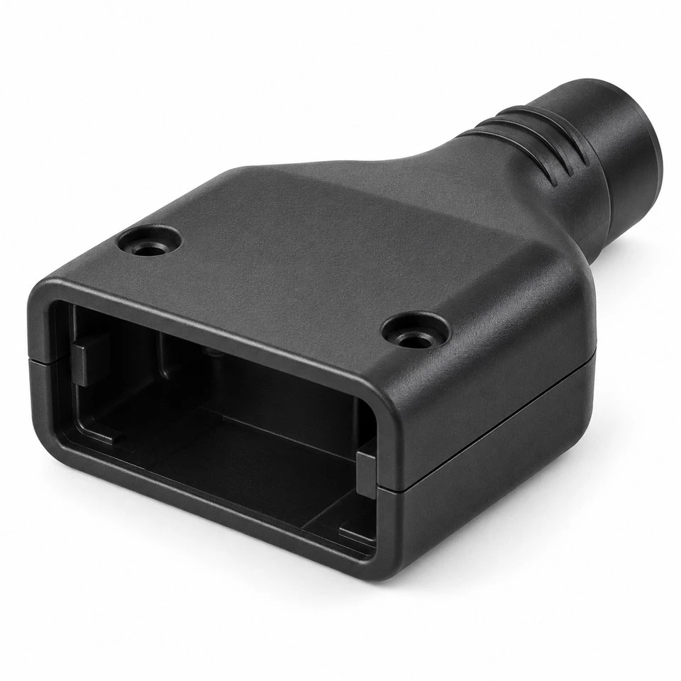
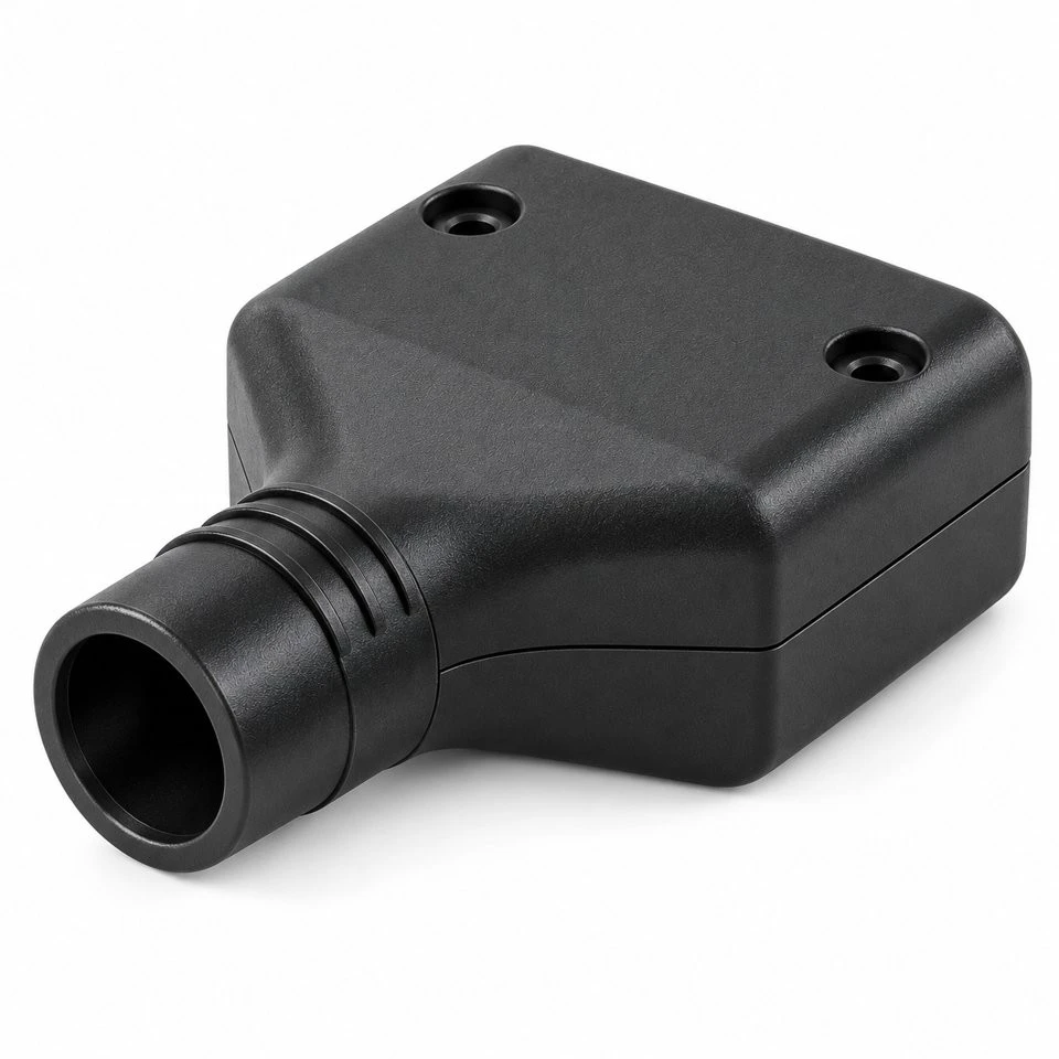
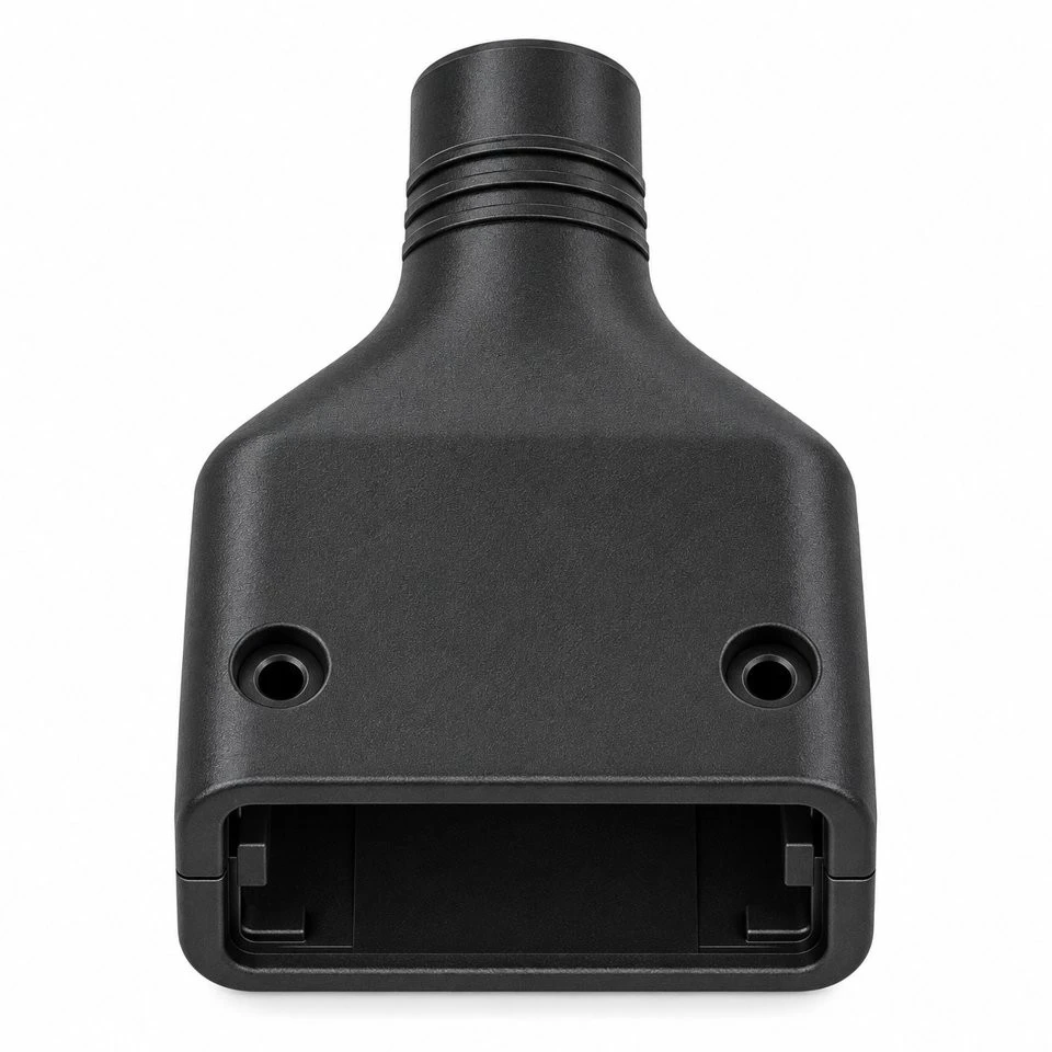
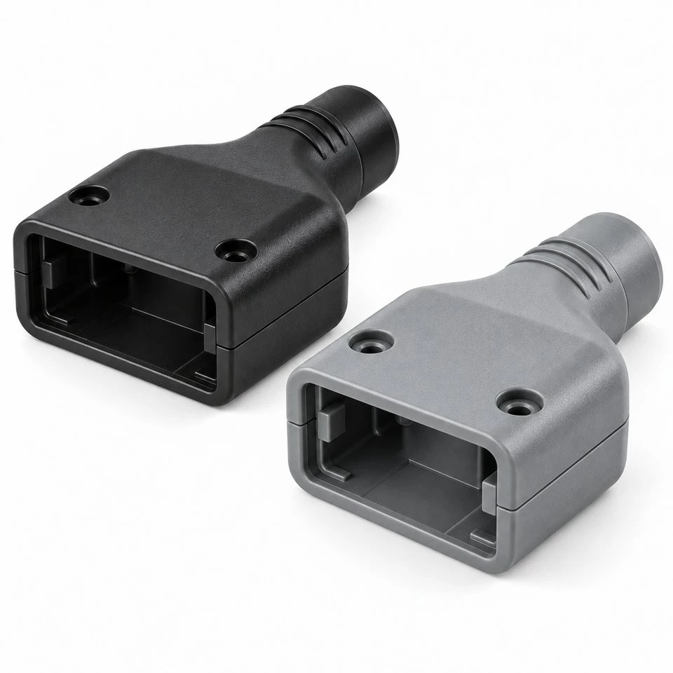
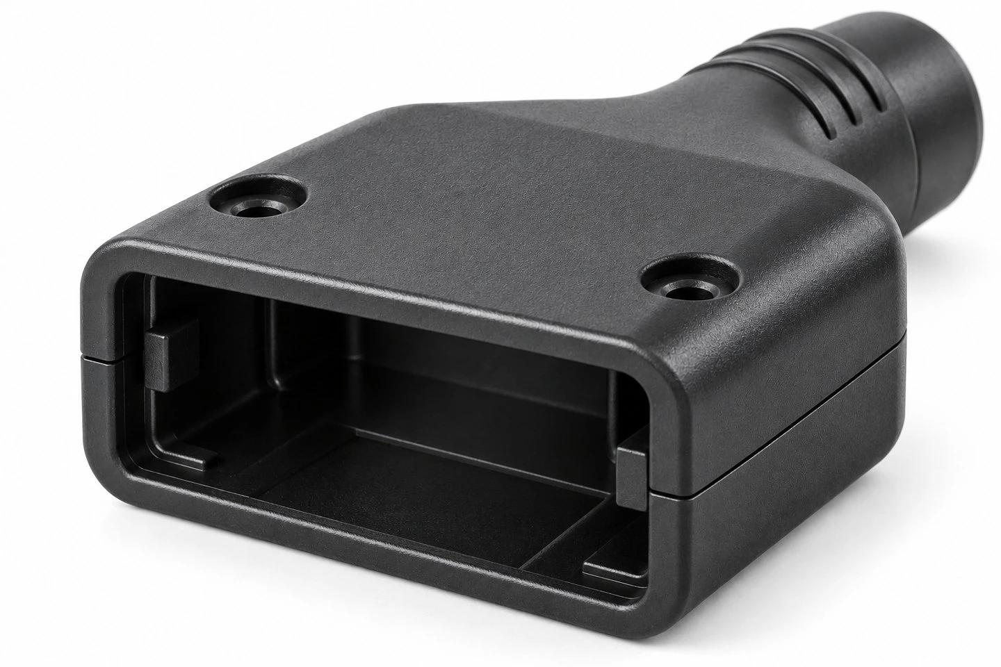
When a cable assembly has an unusual connector outline or limited installation space, its outer housing may need to be designed specifically for the equipment. Our custom injection molded connector backshells provide a drawing-based approach to the mechanical body around that connection. The illustrated concept has a rounded rectangular front opening, a tapered rear section and a circular cable exit. Two molded halves form the enclosure, with recessed fastening positions and a visible joint around the body.
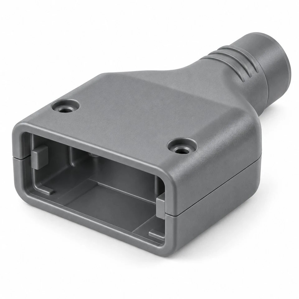
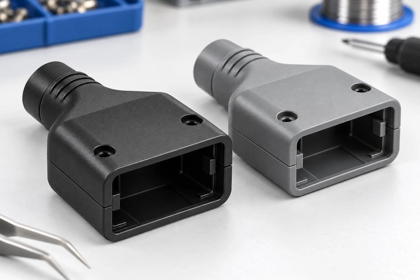
This product is the plastic housing component. Contacts, connector inserts, cables, clamps and fastening hardware are included only when they are expressly listed in the quotation. The photographs illustrate possible black and gray molded appearances rather than a stocked connector standard. Each project starts with the connector interface and cable arrangement, allowing the housing to be developed around the customer's assembly instead of assuming compatibility from a similar external shape.
Where does the backshell fit within your cable assembly?
A clear assembly drawing is the best starting point. Show the connector body that sits at the front, the termination area behind it and the cable leaving the rear. Mark the surfaces used to locate the shell and the parts that remain accessible after closure. This separates the housing's mechanical role from the electrical function of the complete connector and helps establish exactly what the molding project must deliver.
Potential projects include equipment harness interfaces, instrument cable housings and custom connection assemblies within industrial machines. The actual operating conditions and acceptance requirements are defined by the buyer. If the shell must fit an existing connector, provide its drawing or a representative physical sample. A part number can help identify the mating component, but the quotation should still state the agreed interface rather than promise unrestricted compatibility with an entire product family.
How is the front connector opening defined?
The width, height, corner form and engagement depth of the front opening determine how the connector body is positioned. Identify whether the insert rests against an internal shoulder, is captured between the halves or is secured by separate hardware. Include any projections, keys or latch clearances on the mating connector. Those small details can control the assembly even when the main rectangular opening appears to have enough space.
Dimension the interface from suitable reference surfaces and distinguish required contact from clearance. If the insert must not move axially, specify the locating arrangement and the permitted movement. Where the front edge must remain behind another part, show that relationship in the assembled drawing. The exterior opening in a product image does not define a standard connector size, and no unprovided pin count or contact layout is assumed for this custom shell.
Why choose a housing made from two separate halves?
A split body allows the designer to consider assembling the shell around the internal termination arrangement. It can also provide access for inspection or servicing when the fastening system is designed for that purpose. State the intended assembly sequence: whether the cable is terminated before the shell closes, whether the connector insert is fitted to one half first and whether any internal pieces must be held in position during closure.
The mating edges should be reviewed as a complete joint. Provide the acceptable external gap, any locating tongue or ledge and the areas where the halves need to seat firmly. Do not rely on the screw positions alone to describe alignment. If the enclosure will be opened repeatedly, explain the service procedure so the fastening method can be reviewed against the expected handling rather than chosen only for initial assembly convenience.
What needs to be known about the rear cable exit?
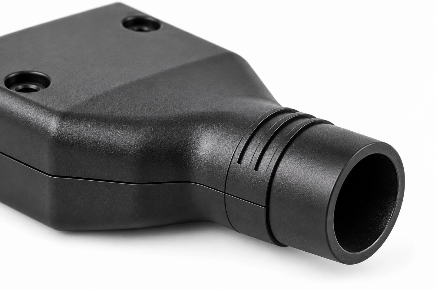
Specify the finished cable outside diameter, its shape and the range of sizes that a single shell must accommodate. A round cable, a bundled group of wires and a sleeved harness can need different internal clearance. Include any connector or preassembled feature that must pass through the exit during installation. The smallest operating cable section may not represent the largest envelope encountered in the assembly sequence.
Show the cable route immediately behind the shell, including nearby panels and required access. The illustrated neck is straight, but alternative exit directions can be discussed as a separate geometry. Provide the required bend path and available space rather than expecting the rear opening to determine cable routing by itself. The exit edge condition should also be specified where contact with a cable jacket is expected.
Does the assembly require a separate cable retention feature?
A cable exit opening and a cable retention system are different features. If the housing must help manage cable movement or transfer pulling forces away from the termination, describe the intended clamp, insert or other retention arrangement. Provide the cable construction and the acceptance test relevant to that function. A hollow rear neck should not be sold as validated strain relief simply because it surrounds the cable.
Where separate hardware is used, identify its dimensions, material and supply responsibility. Show how it is held during assembly and whether access is required after the shell is closed. Include any restrictions on compression of the cable jacket. The molding quotation can then distinguish the shell geometry from the additional items and assembly work needed to achieve the complete retention requirement.
How should the recessed screw positions be specified?
The concept includes two recessed fastening positions near the wider end of the body. Their final locations should account for the internal connector space, tool access and the joint between the halves. Provide the screw type, head envelope and fastening method. If a metal insert or captive nut is required, specify it rather than treating all small screw holes as equivalent features.
State whether hardware must remain captive during service and whether assembly uses controlled torque. Any torque value or repeated opening requirement needs to be reviewed for the selected design and material. The drawing should identify the important boss dimensions and contact surfaces. A quotation should not attach a universal tightening value to every custom backshell, since the fastening system is part of the complete mechanical design.
Which polymer should be specified for the molded shell?
ABS is one option for the housing concept shown. The final grade should be selected against the customer's requirements, including operating conditions, appearance and any applicable material restrictions. Send an approved resin designation if one already exists. For a new project, describe the actual exposures and requirements so alternatives can be evaluated without assuming that a black housing must use a particular material.
Nylon, PP, PC, POM and other polymers can be discussed where appropriate, subject to a review of the shell, its mating features and the tooling. Materials should not be substituted solely on the basis that the model looks unchanged. If electrical characteristics, flame classification or traceability are required, identify the exact specification and the documentation expected. Those requirements apply to a defined grade and application, not automatically to every member of a polymer family.
What about shielding, water exposure and special performance?
This listing describes custom plastic injection components, not a certified connector system. A plain polymer shell does not establish electromagnetic shielding, and the visible joint and cable opening do not establish an ingress rating. If the project needs shielding provisions, seals or another special feature, send the relevant assembly design and required evaluation criteria before the manufacturing scope is finalized.
The same principle applies to temperature exposure, cleaning agents and mechanical handling. Provide named substances, exposure duration and the conditions used for acceptance. Where performance depends on the connector insert, cable or a separate seal, include those items in the review. The required outcome should be verified on the appropriate finished assembly rather than inferred from the outer shell's appearance.
How can the appearance and identification be controlled?
Black and gray are shown as illustrative color options. A controlled color should be agreed against a physical reference or specified standard. Identify the visible outer surfaces and the areas hidden after installation so the appearance review matches the product's use. Texture, gloss preference and acceptable molding marks should be included in the approved information instead of left to interpretation from a screen image.
Part numbers, revision identifiers or simple orientation marks can be considered where there is space. Keep them away from connector seating surfaces and critical joint areas unless the design explicitly allows otherwise. Provide the exact text and its intended reading direction. If the equipment family uses several similar shells, a clear part identification and packaging plan can help distinguish them during assembly and service.
What should first samples demonstrate before production release?
Evaluate the shell with the intended connector and cable arrangement. Confirm that the insert seats correctly, the halves close without trapping wires and the fastening tools can reach the screws. Check the cable exit through the full installation sequence. Where service access is required, open and reassemble the sample using the agreed procedure rather than judging accessibility only from the loose molded pieces.
The inspection plan should identify the front interface, internal clearance, fastening locations, joint condition and cable exit dimensions that matter to the assembly. Appearance can be compared with an approved reference, while functional requirements use separately agreed tests. Record the drawing revision and any deviations clearly. Sample approval should resolve those points before repeat orders are produced, especially if the cable or connector source may change later.
How can you start a custom connector backshell project?
Send an STP, STEP or IGS model, a dimensioned drawing and the mating connector information. Add cable details, material preference, color, quantity and expected repeat demand. If you are replacing an existing shell, explain the issue that the new design should address. Photos are useful for understanding the installation, while the final manufacturing specification should identify the dimensions and interfaces that control fit.
We review the molded housing scope, tooling requirements, sample arrangements and any requested secondary work for the specific project. Minimum order quantity and timing are confirmed with the quotation. Please identify all hardware or assembly items expected in the delivery so the offer remains clear. We welcome inquiries with drawings, preferred material and quantity requirements.
Send your drawings, material and quantity requirements for a custom quotation. Contact: amanda@tjswks.com
Hot Tags: custom injection molded connector backshells, China, suppliers, manufacturers, factory, bulk, cheap, low price, quotation, abs assembled fittings, abs complex fittings, abs matte components, abs orange components, abs small fittings, abs transparent fittings


