




Tianjin SWKS Technology & Development Co.,Ltd is one of the most reliable manufacturers and suppliers of custom abs industrial pneumatic control unit housing in China. If you're going to buy bulk cheap custom abs industrial pneumatic control unit housing, welcome to get quotation from our factory. Quality products and low price are available.
Custom ABS Industrial Pneumatic Control Unit Housing
This custom ABS component is developed around the installation space, mating parts, operating cycle, and drawing requirements of an industrial machine. The photographs on this page are illustrative product concepts. Final geometry, color, dimensions, and surface appearance are agreed during project review.
Product Configuration
| Item | Project definition |
|---|---|
| Product | Custom ABS Industrial Pneumatic Control Unit Housing |
| Material | ABS; specific grade and any reinforcement require engineering confirmation. |
| Manufacturing | Custom injection molding with tool construction based on the approved component drawing. |
| Dimensions and interfaces | Customer-defined mounting features, working surfaces, clearances, and inspection datums. |
| Drawing formats | STP, STEP, or IGS three-dimensional files, accompanied by a dimensioned drawing where available. |
| Quality review | Sample dimensions, fit, appearance, and application trials are agreed before production approval. |
Plastic Shell for a Pneumatic Control Unit
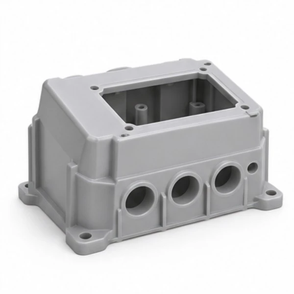
The custom ABS pneumatic control unit housing is a molded enclosure developed around the customer's pneumatic and control layout. The illustrated concept contains a broad shell, panel opening, internal fixing regions and entry features. It does not include a valve block, regulator or electronic equipment. The final geometry follows the approved assembly design. The product title identifies the intended component category without assigning a pressure rating or a sealing certification to the plastic exterior.
A pneumatic control assembly can contain several interfaces within a small space. Provide the selected equipment envelopes and the intended routing so the supplier can review the relevant boundaries. The outside size alone does not explain how a panel, a tubing connection and an internal mounting point interact. The technical package should connect these requirements before the manufacturing version is released.
Panel Region and Operator Access
The panel opening should match the specific interface selected by the equipment designer. It may provide access to an indicator, control or separate front component according to the customer layout. The concept image does not establish compatibility with a particular instrument. Show the insertion path, retention boundary and any clearance needed behind the panel.
The visible front face and the rear seating region can require different acceptance criteria. The customer can identify which surfaces remain exposed after installation and which surfaces establish fit. This makes an appearance reference more useful and helps a tooling discussion address the actual interface. A modification to an opening corner should be reviewed against the selected panel before being accepted for manufacture.
Space Around Pneumatic Components
The shell surrounds the pneumatic components specified by the customer, but it is not automatically part of their pressure boundary. Identify the actual role of each plastic surface in the assembly. If the design includes a pressurized molded feature, that feature and its complete validation requirements must be specified separately rather than inferred from an enclosure title.
A valve block or regulator may need room for tubing, connectors and adjustment access beyond its bare outline. Include those full installed envelopes. A component that fits inside the empty shell can still obstruct the assembly tool or a service operation. The customer can describe the installation sequence and any necessary access direction so the supplier reviews the intended control unit arrangement.
Tubing Entries and Routing Boundaries
Entry openings can be positioned to suit the chosen pneumatic routing. Their count, diameter and local wall geometry follow the released drawing. The illustrative openings do not imply a supplied fitting, thread standard or universal tube compatibility. Provide the selected connection references and the space needed around them, including the direction from which a mating part is installed.
If a cable and a tube use neighboring regions, identify their respective clearance envelopes. This helps avoid a layout assumption based only on the visible entry positions. Any separate strain relief, bracket or sealing element should be included in the supply scope where required. The housing specification can then distinguish molded geometry from accessories installed as part of the complete equipment.
Mounting Supports and Shell Closure
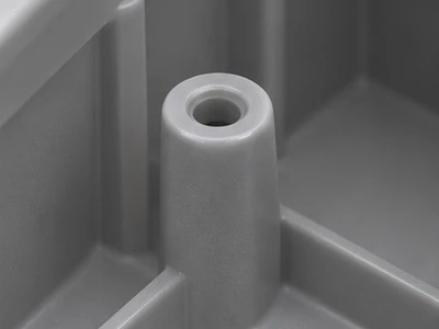
Internal fixing points should correspond with the equipment and fastening method chosen by the designer. State the boss geometry, hardware reference and any insert requirement on the print. A concept rendering does not establish an allowable tightening torque or a service load. The supplier can review the actual arrangement and discuss proposed amendments at the supports before they become part of the production model.
The closure joint also needs a defined relationship with the internal equipment. Identify the seating face and any region that must remain clear. If a gasket is required, provide its separate specification and installed geometry. A clean molded rim does not establish a tested ingress rating. The application owner defines and evaluates the performance of the completed pneumatic control unit.
ABS Appearance and Variant Identity
The images use a neutral grey ABS appearance to explain the shell and its mounting features. They are illustrative product renderings rather than photographs of a completed control unit. The actual compound, shade and finish are agreed for the order. If a visible face must match another machine component, provide a physical or agreed color reference and the relevant appearance criteria.

Maintain separate references for versions with different panel openings, entry patterns or internal supports. Similar outer shells are not automatically interchangeable. The quotation can identify the selected ABS specification, tooling scope and quantities for each accepted configuration. Submit the appropriate enclosure and mating files so the review addresses this pneumatic control unit housing and its actual assembly boundaries.
Map the Pneumatic Unit Before Defining the Shell
A pneumatic control enclosure surrounds the customer's selected valve or control arrangement. Establish the positions of the equipment, tubing connections, electrical connections, and service access before finalizing the ABS outline. The enclosure is not itself advertised as a pressure vessel. If the supplied plastic has any pressure containing function, that requirement needs a separate engineering review and acceptance definition. The illustrated shell represents a housing component around equipment specified by the buyer.
Different tubing routes can produce very different wall requirements. A tube may pass through a simple clearance opening, a separate bulkhead fitting, or an assembly mounted to an internal bracket. Identify which arrangement applies to each location. The molding quotation should not infer threads, sealed ports, or a fitted connector from a round opening in a concept picture. Provide the actual interface drawing and installation envelope for the purchased hardware.
Leave Room for Tubing Installation and Replacement
Tube access involves more than the diameter of the opening. Consider the space needed to insert the tube, operate the connector release, and route the tube after connection. A fitting can be accessible in an empty shell and difficult to service after the full unit is assembled. Review the installation with adjacent fittings and covers in place. The customer can identify the access regions that the enclosure must preserve throughout its intended service sequence.
The routing also affects the lid arrangement. Tubing that crosses a lid separation line can complicate opening the enclosure. If equipment must remain connected during routine inspection, define how the cover moves and where it rests. A hinge, removable panel, or separate cover is a design choice for the actual project. The image is an illustrative enclosure and does not establish any particular moving cover mechanism.
Distinguish Ventilation From Ingress Protection
A control housing may need openings for access, drainage, or thermal management. The intended purpose of each opening should be explicit. A vented wall and a sealed wall serve different application needs. Neither a smooth ABS surface nor a close fitting lid demonstrates a tested enclosure rating. If an ingress requirement applies to the completed unit, define the full assembly, seals, fittings, and qualification method that establish it.
The mounting position can influence how openings are exposed. A wall facing downward in one installation may face wash spray or debris in another. Provide the intended orientation and surrounding machine layout rather than describing the application only as industrial. The enclosure review can then focus on the specific geometry the buyer needs. Final environmental suitability remains tied to the selected material and tested assembly configuration.
Support Internal Hardware at Defined Locations
Internal mounting features should correspond to the actual control hardware or its separate support plate. Show the mounting centers, supported surfaces, and any restrictions around moving or removable components. A boss should not be assumed to support every control unit with a similar outside size. If the product family contains several valve layouts, identify whether separate housing versions are needed or whether a common internal plate is specified by the customer.
Fasteners and inserts can affect the surrounding molded geometry. Define whether hardware is included and how it is installed. A sample trial should use the intended assembly method and record any spacers or local adjustments. This prevents an improvised bench installation from becoming an undocumented production expectation. The accepted drawing can distinguish a controlled mounting face from an exterior region with only an appearance requirement.
Identify the Service and Receiving Configuration
For a multi-part housing, give the body and lid clear references. A common cover may be compatible with more than one body, but that relationship should be documented. Color alone is a poor identifier when different tube entry patterns are used on the same machine line. Packaging labels and the buyer's part number can establish the configuration without adding unwanted marks to a visible enclosure face.
Request the quotation with the ABS grade requirement, shell files, internal equipment references, and requested quantities. Include any labels, secondary openings, or hardware installation that belongs to the supplied component. The price and sample schedule follow the agreed scope. The rendered grey appearance does not indicate an existing stock item or an already qualified pneumatic control assembly; final details are approved for the customer's project.
Related Engineering Resources and Inquiry
Explore our custom plastic injection parts or read our guide to selecting engineering plastics for gears, rollers, and sliding components. Send the drawing, target quantity, mating information, and application conditions to amanda@tjswks.com or call 0086-15222707659 for project review.
Hot Tags: custom abs industrial pneumatic control unit housing, China, suppliers, manufacturers, factory, bulk, cheap, low price, quotation, ABS Injection Moulding Plastic Parts, automotive plastic injection parts, Design PC Injection Molded Machine Plastic Parts, durable plastic injection parts, PP Plastic Parts For Plastic Special shaped Parts, Small run injection molding


