





Tianjin SWKS Technology & Development Co.,Ltd is one of the most reliable manufacturers and suppliers of custom pc industrial machine vision camera mounting housing in China. If you're going to buy bulk cheap custom pc industrial machine vision camera mounting housing, welcome to get quotation from our factory. Quality products and low price are available.
Custom PC Industrial Machine Vision Camera Mounting Housing
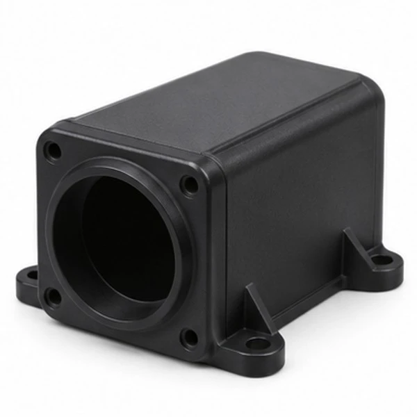
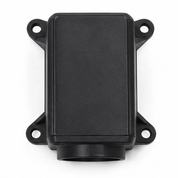
This custom PC component is developed around the installation space, mating parts, operating cycle, and drawing requirements of an industrial machine. The photographs on this page are illustrative product concepts. Final geometry, color, dimensions, and surface appearance are agreed during project review.
Product Configuration
| Item | Project definition |
|---|---|
| Product | Custom PC Industrial Machine Vision Camera Mounting Housing |
| Material | PC; specific grade and any reinforcement require engineering confirmation. |
| Manufacturing | Custom injection molding with tool construction based on the approved component drawing. |
| Dimensions and interfaces | Customer-defined mounting features, working surfaces, clearances, and inspection datums. |
| Drawing formats | STP, STEP, or IGS three-dimensional files, accompanied by a dimensioned drawing where available. |
| Quality review | Sample dimensions, fit, appearance, and application trials are agreed before production approval. |

Housing Around a Machine Vision Camera Envelope
The custom PC camera mounting housing is a molded plastic enclosure reviewed around the machine vision equipment selected by the customer. The illustrated concept shows a front aperture, a compact body, attachment lugs and a rear closure. It contains no lens or electronic assembly. The camera designer defines the actual optical, mechanical and service boundaries. SWKS supplies custom molding according to the accepted model and print rather than claiming universal compatibility with every industrial camera.
Provide the complete camera envelope, including connectors and any separate mounting hardware. That reference explains which internal surfaces locate the equipment and which regions simply provide clearance. The outside appearance alone does not establish the position of the optical axis or a permitted adjustment. Those relationships belong to the customer design used for the manufacturing discussion.
Front Aperture and the Optical Path
The front opening must correspond with the selected lens arrangement and the space needed around it. The concept aperture is illustrative and does not specify a lens mount standard or an optical tolerance. Show the actual neighboring surfaces and any restricted region around the optical path. A molded opening can have a mechanical role without being an optical surface itself.
If the project includes a separate window, bezel or lens mount, identify that component and its interface. The appearance of a circular opening should not be taken as evidence that glass, a threaded metal fitting or another accessory is included. The quotation can list those items separately where they are part of the agreed supply scope. Preserve the approved interface reference with the housing model.
Camera Orientation and Attachment Lugs
The external lugs connect the enclosure with the mounting structure selected for the equipment. Their positions, hole geometry and seating faces should match the actual installation. A concept picture does not establish a fastener size, vibration rating or positional repeatability. Supply the mounting bracket and hardware references so the molded support boundaries can be reviewed against the intended arrangement.
The equipment owner can also identify any adjustment used during camera alignment. Document the allowed adjustment and the accepted final condition rather than assuming that the shell alone establishes the camera position. A sample trial can record the orientation and neighboring part revisions. That record helps distinguish a molding observation from an adjustment or support change made during installation.
Internal Support and Connector Access
The camera body may have features that extend beyond its primary fixing points. Include those complete boundaries when defining the available internal space. A rear connector can also require room for its mating plug, cable bend and service access. The housing should therefore be reviewed with the assembled connection rather than only with an unplugged camera outline.
Where internal bosses or ledges locate equipment, identify the active surfaces and their measuring references. Where a feature is only clearance, define the boundary that must remain clear. This distinction allows the tooling team to assess a proposed local amendment without imposing an undefined precision requirement on every interior wall. The customer design establishes which characteristics need particular attention during sample inspection.
PC Compound and Visible Surface Requirements
PC is the requested polymer family for the housing. The selected compound and color should correspond with the customer's environment and qualification requirements. A black molded PC enclosure is not automatically a transparent optical component, nor does the generic material name establish a tested temperature or impact rating for every formulation. State the required material designation and supporting documents when those are part of the order.
The visible exterior may need a defined texture, color reference or marking area. Identify those requirements with agreed viewing conditions. The front aperture and any restricted equipment contact region can have separate criteria. The production finish follows the accepted tooling and sample specification. The clean highlights in a rendering do not establish a measured gloss or a permitted dimensional variation at the camera interface.
Rear Cover and Maintenance Sequence
The closure layout should suit the way the selected camera is assembled and serviced. The customer can identify whether the rear cover is opened during installation, routine maintenance or only a defined repair procedure. Show the intended joint and access to its fixing hardware. A plain rim does not establish an ingress rating or a tested sealing performance for the completed unit.

If a gasket, window or separate bracket is required, include its controlled reference and the relevant installed condition. The illustrated component remains a plastic housing concept. Send the released enclosure and mating files, PC grade and requested quantities so the supplier can review the real machine vision housing configuration and identify any proposed design amendment before tooling proceeds.
Start With the Camera's Mechanical Reference
A vision camera housing must be defined around the selected camera reference, lens arrangement, and mounting method. The outside shape should follow those interfaces. A camera body can have a stepped outline, projecting connectors, and fasteners that require space beyond the nominal body width. Supply the complete installation drawing rather than a product photograph alone. If several camera versions will share the enclosure, list the differences and identify whether one common housing is actually required.
The mounting reference should be distinguished from the cosmetic outer surface. A clear or translucent PC wall may look suitable for alignment in a rendering, yet the camera position should be established by the specified mechanical datums. An appearance face is not automatically a precision locating surface. Identify the pads, shoulders, holes, or separate brackets that determine position. The molded component can then be inspected against the references used by the machine designer.
Keep the Lens and Lighting Envelope Clear
The front opening must allow the intended lens and any separate retaining hardware to fit without interference. Review the lens envelope through its permitted adjustment range, including focus or aperture access where applicable. If the camera uses a separate illumination assembly, show its position and the space needed for installation. A housing that clears a bare lens can still obstruct adjustment or the mounting arrangement of a light.
The concept does not establish an optical window specification. Transparent PC used as a structural housing is not automatically suitable for a calibrated imaging path. If the design requires light to pass through the molded wall, the optical requirements must be supplied separately. Surface form, texture, local thickness, and processing effects can matter to that application. The customer should define how the completed optical arrangement will be evaluated before the wall is treated as part of the imaging system.
Plan Cable Access Around the Installed Machine
Camera connectors are often larger than the cable itself. Show the plug body, locking method, and the cable bend region behind the camera. Consider whether the connector is installed before or after the camera is placed into the housing. Those assembly sequences can require different opening sizes. A removable cover may provide access without making the final housing opening unnecessarily large, but the actual arrangement follows the approved design.
Maintenance access also depends on the location of the surrounding machine structure. An otherwise accessible connector may face a guard or supporting frame once the housing is mounted. Include that boundary in the installation review. The molded housing supplier can assess its own geometry, while the equipment owner verifies the full installation. Record any adjustment used during the trial so it is not mistaken for a nominal clearance in the component drawing.
Review Clamp Loads and Positional Repeatability
Fastener tightening can affect local deformation of a polymer mounting region. The design should identify how the camera and housing are supported, how the fasteners transfer load, and whether spacers or inserts are part of the assembly. Do not rely on an unspecified tightening force to produce the desired alignment. The machine owner defines the assembly procedure and acceptable positional behavior, with the component supplier reviewing the molded interfaces against that procedure.
If repeatable removal and refitting are important, include that operation in the sample evaluation. Record the camera reference, support fixture, hardware, and measurement method. A photograph of a camera installed once is not a repeatability study. The trial can establish whether the agreed mounting arrangement is suitable for the application without making a universal accuracy claim about every PC camera housing.
Define Appearance Without Implying Optical Certification
Specify the intended PC grade, color, clarity, and texture as separate project requirements. A clear rendering illustrates the model and does not prove optical quality, chemical resistance, or outdoor suitability. Identify cleaning agents and exposure conditions relevant to the machine location. Material compatibility and finished assembly suitability require confirmation for the actual formulation and use conditions. The supply scope can include the documentation agreed for the resin without claiming unrequested approvals.
For incoming inspection, distinguish unacceptable surface defects from ordinary process features allowed outside the camera's functional boundaries. If a gate witness, joint line, or ejector mark must avoid a mounting pad or viewing region, identify that restriction before tool construction. The approved appearance sample and dimensioned print can then work together. Neither document should be expected to replace the other.
Related Engineering Resources and Inquiry
Explore our custom plastic injection parts or read our guide to selecting engineering plastics for gears, rollers, and sliding components. Send the drawing, target quantity, mating information, and application conditions to amanda@tjswks.com or call 0086-15222707659 for project review.
Hot Tags: custom pc industrial machine vision camera mounting housing, China, suppliers, manufacturers, factory, bulk, cheap, low price, quotation, Custom ABS PP POM Nylon Injection Molding Part, injection molded plastic parts, Low Quantity Injection Molding, plastic injection components, plastic injection manufacturing parts, plastic injection molding parts


