


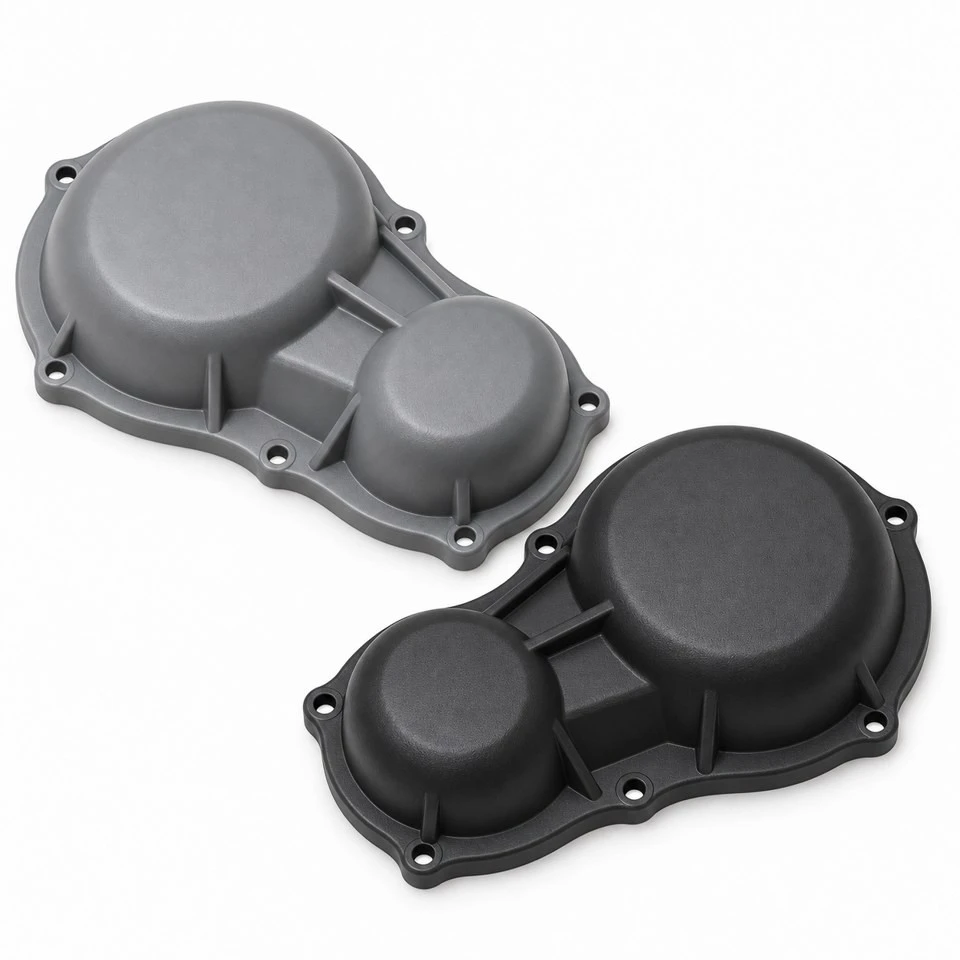
Tianjin SWKS Technology & Development Co.,Ltd is one of the most reliable manufacturers and suppliers of custom injection molded plastic gearbox covers in China. If you're going to buy bulk cheap custom injection molded plastic gearbox covers, welcome to get quotation from our factory. Quality products and low price are available.
Custom Injection Molded Plastic Gearbox Covers
When a machine builder changes a drive arrangement, the surrounding cover often needs to change with it. An existing metal or plastic shell may interfere with a bracket, leave insufficient clearance around a fastener or take too long to remove during maintenance. SWKS develops custom injection molded plastic gearbox covers around the equipment layout, bringing the external contour, mounting flange and internal clearance into one drawing-based component. ABS, nylon and PP are among the material families that can be assessed for the specified operating conditions.
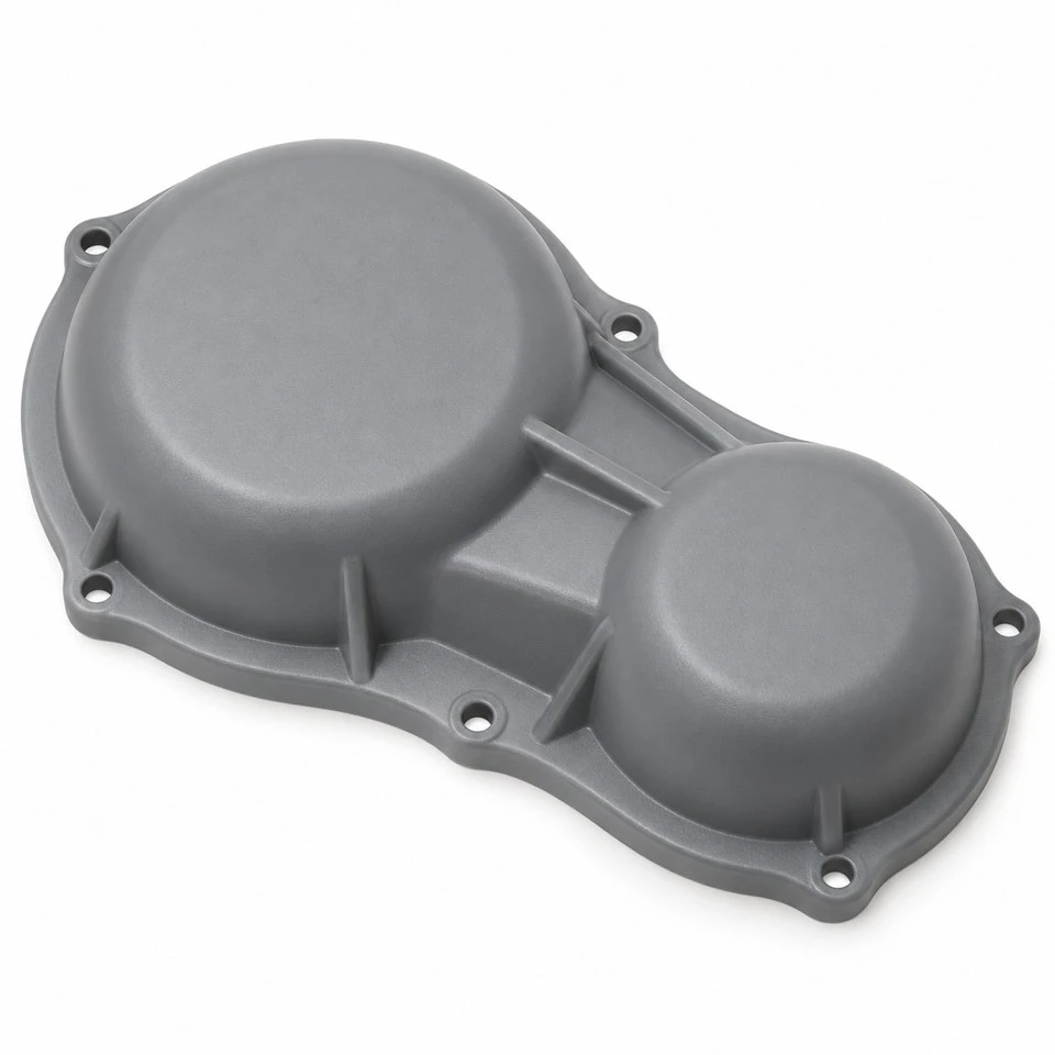
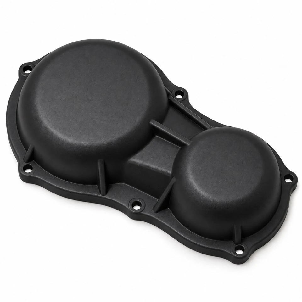
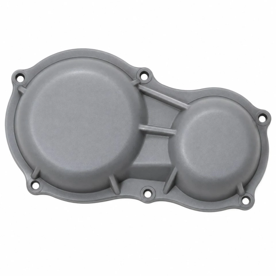
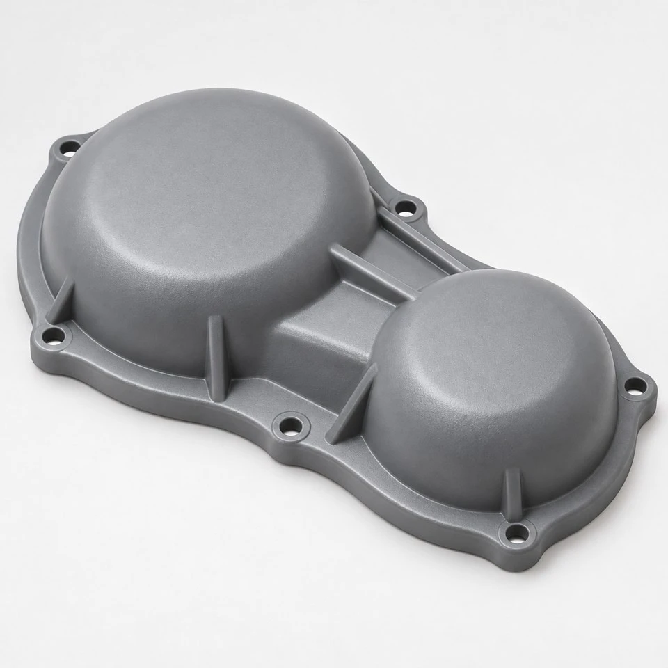
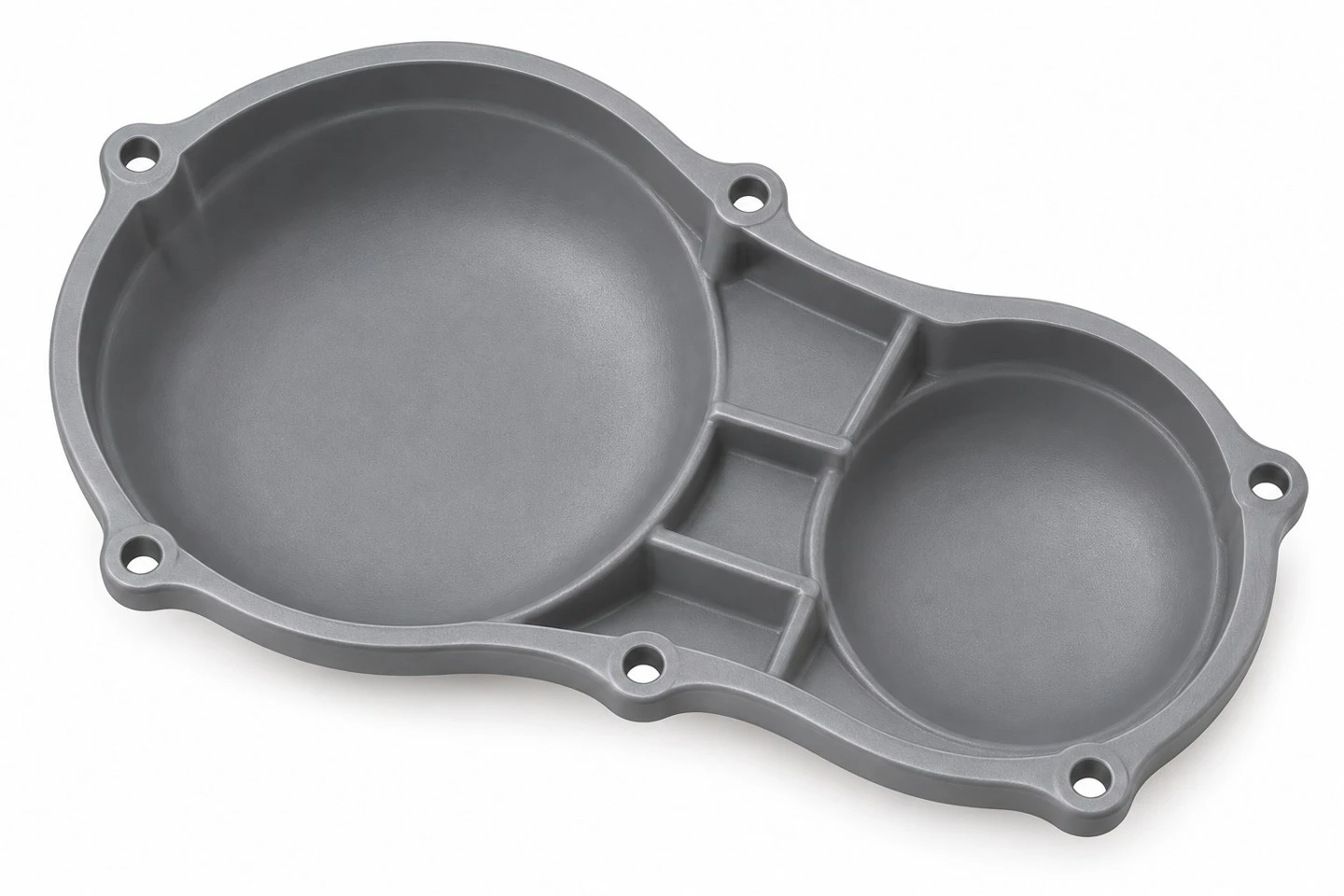
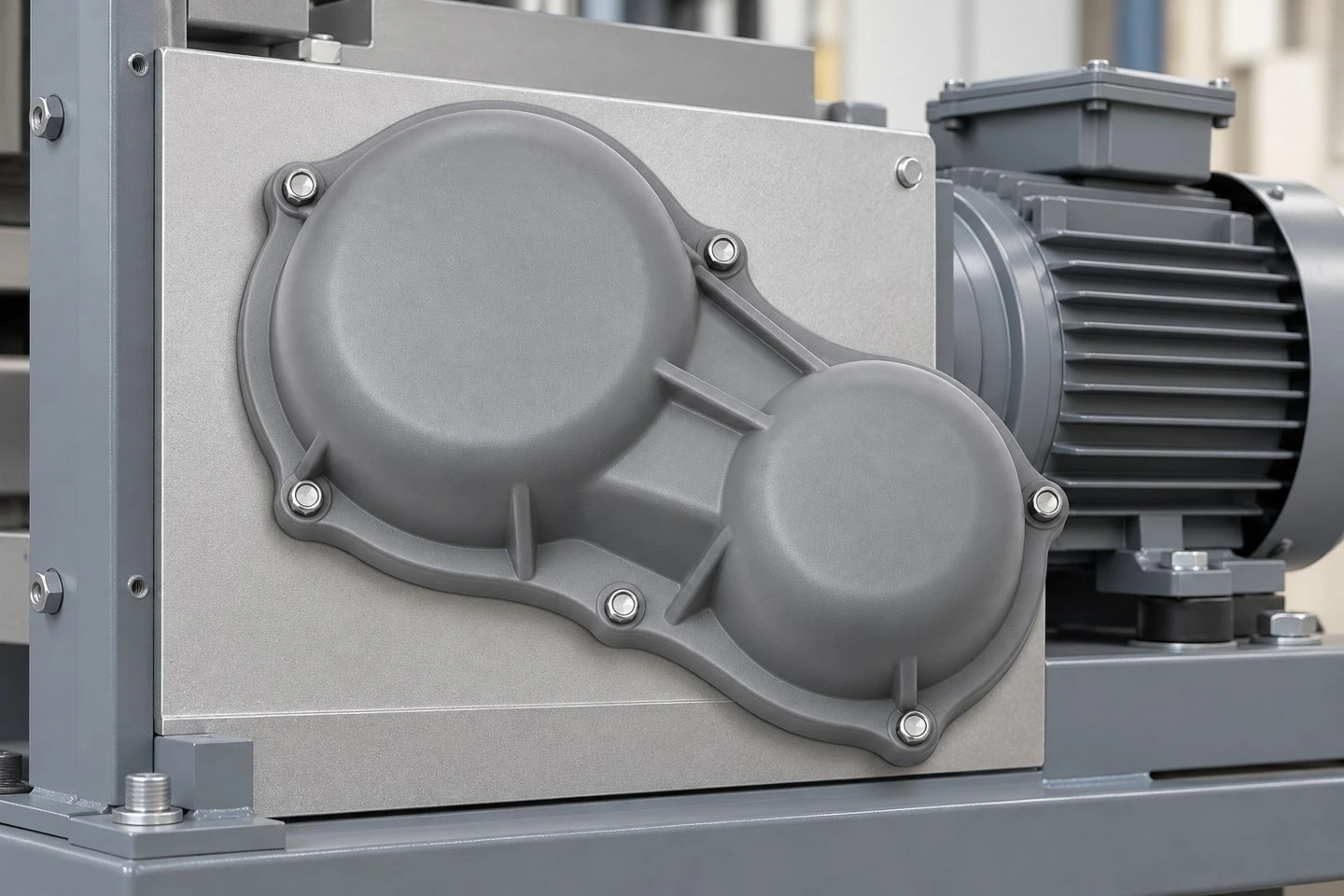
The illustrated two-lobed shell is an example of an external cover for a compact mechanical drive assembly. Its closed outer face, shaped clearance envelope and perimeter flange show how a custom molded cover can follow the machinery instead of using a generic electrical box. The component is offered as a custom enclosure or outer cover. A load-bearing gearbox housing, an oil-retaining closure and a validated machine safety guard involve additional requirements that must be separately defined in the project specification.
What makes this cover suitable for a machinery project?
The value of a custom cover is the fit between the shell and the complete machine. A formed clearance envelope can accommodate the outside shape of a drive unit, while a flange provides defined attachment points on the surrounding structure. The design can reserve space for nearby mounting brackets and service tools. A smooth exterior can also give the machine a more finished appearance without requiring the cover to carry the loads of the internal transmission.
Possible projects include outer covers for compact reduction units, packaging-machine drives, conveyor drive modules and other enclosed equipment mechanisms. These are application directions, not an assertion that one illustrated shape fits all of them. Please provide the relevant assembly envelope and the cover's intended function. We then review which surfaces locate the part, where it fastens and what it must clear when the equipment is running or being serviced.
Which cover features can be developed from your drawing?
The overall outline, depth and internal cavity can follow your equipment arrangement. Raised areas can create clearance above local protrusions, while a continuous mounting flange can be shaped around the available attachment surface. Hole locations, recessed fastener areas, locating steps, external ribs and edge radii can be incorporated where the design needs them. Openings or cable exits can also be reviewed when required, although they are not part of every cover design.
We start with the functional interfaces rather than adding features for appearance alone. A locating lip should have a defined mating surface. A rib should support a particular panel area without obstructing the mechanism. A fastener recess should match the screw head and the installation tool. This approach helps turn a rough cover concept into a component that is easier to quote, tool and evaluate in the machine.
How should the internal clearance envelope be specified?
Send a model of the parts that sit beneath the cover, including the maximum positions of moving components where relevant. The clearance model should account for assembly tolerances, movement, possible deflection and access for installation. Checking only the nominal shape of a stationary gearbox can miss a shaft end, a fixing screw or a nearby bracket that occupies more space in the finished assembly.
Identify the keep-out areas on the drawing or model. These can include rotating parts, hot surfaces, lubrication points and connectors that require access. Where the cover is fitted after the drive unit is installed, show the direction in which it approaches the machine. A cover that fits in its final position may still be difficult to install if it cannot pass over an adjacent component. The removal path deserves the same attention as the installed clearance.
When is ABS a practical material to evaluate?
ABS can be assessed for indoor machinery covers where a molded exterior, consistent appearance and an integrated shell structure are useful. The selected grade must match the actual temperature, impact and chemical exposure requirements. A cover on a clean indoor assembly line has different needs from a shell near lubricants, cleaning fluids or a hot drive surface. Providing those conditions makes the material discussion more useful than requesting ABS by name alone.
For ABS injection molded plastic parts, we also review how the visible exterior is to be specified. Color reference, gloss level, permitted flow appearance and the position of gate or ejector marks should be agreed before mold finishing. If painting, printing or a separate label area is needed, state that at quotation. These options can affect surface preparation, handling and inspection, so they should be treated as defined process requirements.
When should nylon or PP be considered instead?
Nylon may be evaluated where the cover has more demanding mechanical attachment features or where a particular grade offers properties required by the environment. Unfilled and reinforced grades should be considered separately. Reinforcement can affect the molded surface and directional dimensional response, while moisture conditioning is relevant to nylon dimensions. A tightly located perimeter interface therefore needs an agreed measurement and conditioning state.
PP can be reviewed for lightweight covers when its grade properties suit the application, including any specified chemical exposure. Panel stiffness, fastening pressure and sustained deformation still need attention. Material selection should consider the entire shell and its installation, not only a sample coupon. If the machine requires a special flame, electrical or environmental classification, send the exact specification. No such classification is implied by the general resin name or by the gray and black concept images.
| Cover requirement | Design information to provide |
|---|---|
| External envelope | Available length, width, depth and nearby equipment boundaries |
| Internal space | Assembly model, keep-out zones and required running clearance |
| Attachment | Mounting centers, screw specification, mating face and installation direction |
| Working conditions | Temperature, impact exposure, oils, cleaners and indoor or outdoor location |
| Finish | Color reference, texture, visible surfaces and any marking area |
| Production definition | Drawing revision, material grade, quantity and agreed inspection criteria |
How are flange flatness and fastener locations handled?
A cover can look correct externally and still be difficult to install if the mounting flange does not sit properly against the machine. Define the mating face, the locating method and the fastener pattern. If the screws only clamp the part, the locating geometry may need to be handled elsewhere. If the screws also locate the cover, their clearances must be coordinated with the equipment tolerances. The drawing should make this arrangement explicit.
For a broad flange, flatness and local thickness need to be considered together with the molding layout. Specify which areas must contact the machine and which areas may remain clear. Recessed screw locations, washers or sleeves can be reviewed when they are needed to control attachment behavior. Tightening instructions and repeated removal requirements also affect the design. We do not assume a universal torque or a fixed screw size for all custom covers.
Does a closed shell automatically provide oil or water sealing?
A closed-looking cover does not by itself establish a seal. If the project requires exclusion of dust or water, define the required performance, the complete mating arrangement and the test conditions. A gasket seat, controlled compression, fastening distribution and the corresponding machine surface may all be relevant. Any stated enclosure rating must be supported by the appropriate evaluation of the assembled system, rather than inferred from the absence of openings.
Oil retention is a separate question. An external protective shell should not be described as an oil-retaining gearbox lid unless it has been designed and validated for that role. Likewise, a cover intended to limit access to moving parts needs the applicable guarding requirements to be established by the equipment designer. SWKS can review the required molded geometry and manufacturing scope once these functions are defined, keeping the quotation aligned with the real component specification.
How can a cover remain convenient to service?
Maintenance access is best considered before the tool is built. Identify which fasteners must be reached, how much space is available for the tool and where a removed cover can be handled safely. The cover may need to clear a fixed bracket without disconnecting unrelated parts. If a technician removes it regularly, the attachment design should reflect the expected number of service operations and the approved fastening method.
A useful review can follow one complete service sequence: stop the equipment, access the fasteners, release the cover, move it away from the drive and reinstall it. This can reveal an inaccessible screw, a difficult lifting edge or a removal path blocked by a cable. An assembly trial with representative hardware provides better evidence than examining the cover alone on a workbench. Any proposed improvement should be confirmed against the equipment requirements.
What is reviewed before making the injection mold?
Shell depth, wall transitions and the relationship between exterior ribs and interior clearance influence the molding approach. The design review considers draft, corner radii, local thick sections and features that may require side actions. We coordinate the mold release direction with the functional flange and locating surfaces. If the proposed geometry makes tooling unnecessarily complex, alternatives can be discussed before the design is frozen.
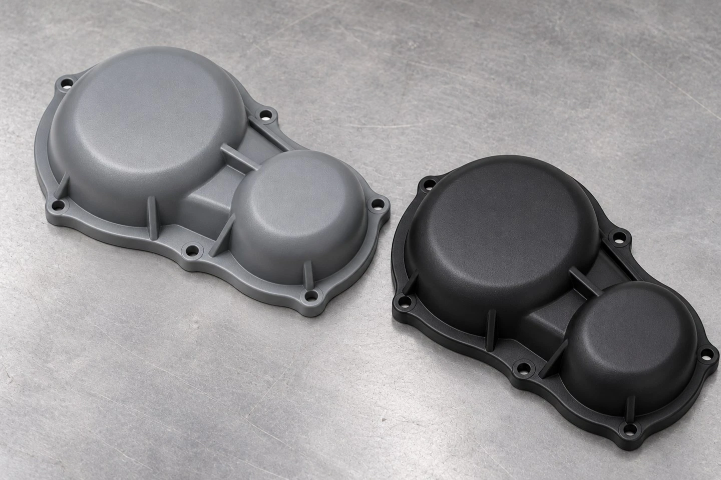
Gate and ejection positions are checked against appearance and assembly. A gate vestige should not sit on a critical mating face or obstruct the cover's installation. Visible marks and permitted parting-line traces should be included in the agreed appearance criteria. The final exterior texture is selected with these requirements in mind. A concept photograph shows the intended product form, while the approved drawing defines the geometry and acceptance conditions for manufacture.
How are first samples approved for the machinery?
Sample approval should combine dimensional checks with an installation trial. Inspect the mounting pattern and the agreed flange areas, then fit the cover to the intended drive assembly. Confirm that the cover sits correctly, that every fastener can be installed and that the required internal clearance is maintained. Where vibration, heat or cleaning exposure matters, specify the relevant evaluation conditions and acceptance criteria.
Record the approved drawing revision, material grade, color and inspection plan before batch production. If a fit trial leads to changes in rib placement, depth or mounting locations, the revised component needs the relevant checks repeated. A change to resin can also affect dimensions and attachment behavior. Documenting these decisions helps keep later orders consistent with the component that was actually approved on the machine.
What information is needed for tooling and production pricing?
Provide a STP, STEP or IGS file, a dimensioned drawing and the required quantity. Include the preferred material and finish, the operating conditions and the critical interfaces. Tooling cost and piece price depend on shell size, mold complexity, material grade, cavity arrangement, secondary operations and inspection scope. If several machine versions need related covers, send the full version list so that shared tooling features can be evaluated.
There is no fixed standard dimension table or universal minimum order for this custom product. Dimensions, order quantity and lead time are quoted for the project. State the first purchase quantity and expected annual demand, as well as the planned sample approval date. This allows mold development and production planning to be considered together. Welcome to send your drawings, material requirements and required quantities for a custom plastic gearbox cover inquiry. Contact: amanda@tjswks.com
Hot Tags: custom injection molded plastic gearbox covers, China, suppliers, manufacturers, factory, bulk, cheap, low price, quotation, durable plastic injection parts, Injection Molded Polypropylene Parts, injection molding plastic, Low Volume Injection Molding Machine, Polyurethane PU Coated Wheel Roller, PP machine parts


