


Tianjin SWKS Technology & Development Co.,Ltd is one of the most reliable manufacturers and suppliers of custom pom industrial rotary table detent cam in China. If you're going to buy bulk cheap custom pom industrial rotary table detent cam, welcome to get quotation from our factory. Quality products and low price are available.
Custom POM Industrial Rotary Table Detent Cam
An injection-molded detent cam designed from your drawing for industrial rotary indexing tables and precision assembly equipment.
| Part material | POM |
|---|---|
| Other materials for custom parts | ABS, POM, PA66, PP, PC, PA, PU, TPE, TPU |
| Processing | Injection molding |
| Drawing formats | STP, STEP, IGS |
| Configuration | Custom part manufactured to the approved product drawing |
Application and indexing function
A detent cam provides a defined mechanical interface between an indexing table and its locating element. Depending on the equipment design, a spring-loaded roller or other follower can enter a pocket as the table approaches a station. The detent geometry can support a repeatable registration point for transferring or assembling a workpiece. A drawing should show which element establishes the station position and which element carries forces while the table is stopped. Share the mechanism layout so the cam can be reviewed in the context of the entire motion cycle.
Machines that look similar can have quite different mechanical requirements. Some tables are driven nearly to the station before the follower seats. Others use a separate locking element after the cam has located the position. Document whether the component serves as a locating feature, a motion-control feature or a replaceable wear interface. Include a marked sketch of rotation direction and identify any alternate index positions, dwell intervals or reverse travel expected in the application.
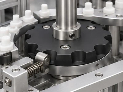
Illustrative rendering. Final part geometry follows the approved drawing.
Cam profile and angular tolerances
The pocket approach, seating region and exit radius should be defined in relation to the follower shape and load. A narrow or steep pocket can change how the follower enters and releases. A shallow profile may need a different approach to position verification. Submit the full contour as geometry when possible, and identify the surface used to define the nominal station angle. On a part with several locations, give the angular position of every pocket relative to a marked reference datum.
Review the position of the keyway, mounting pattern and center bore as a coordinated interface. A bore that locates on a hub can establish the rotation axis, while a key or dowel can control clocking. Mounting screw clearance can affect assembly repeatability when no positive locating feature is used. The equipment team should identify which dimensions determine the assembled profile and which dimensions can use normal molded tolerances. Check radial runout and axial seating against the mating assembly.
Material, contact and wear
POM is often considered for guides and repetitive sliding or rolling interfaces. Material grade selection depends on the contact pair, lubrication policy, temperature and expected cycle count. A steel follower with a polished surface can behave differently from a polymer roller or a worn follower. Provide the follower material and finish, its diameter and the intended contact arrangement. If the cam operates around abrasive debris, cutting fluids or cleaning agents, describe the frequency and duration of contact.
On an existing part, record whether wear occurs on the approach ramp, in the seated pocket or on the exit face. The position of the wear can guide review of alignment and contact load. Ask the sample team to photograph both the cam and follower before and after a representative trial. Changes in locating repeatability, operating noise or follower movement should be recorded alongside visual observations. Material choice can then be reviewed using actual performance in the equipment.
Molding review for a shaped cam
A tooling review considers how the working contour, central bore and mounting features will be formed. Parting direction can influence whether a pocket and its adjoining radius are accessible from the same mold half. A stepped hub or an undercut may affect the tooling approach. Provide the section view through the thickest and thinnest regions so sink or differential cooling can be discussed before a steel design is released.
A gate or ejector witness should be located with reference to the wear surfaces, hub seating face and inspection datums. If a contact edge must remain smooth across a particular section of the profile, mark that area on the drawing. The project review should also record whether balance, appearance or identification marks matter for the intended equipment. Confirm any secondary operation and its acceptance criteria in the same drawing package.

Illustrative rendering. Final part geometry follows the approved drawing.
Inspection and machine trial
Inspection can include bore size, mounting-hole pitch, pocket angles, thickness at the contact area and runout of the working profile relative to the intended axis. Agree on whether the cam should be supported through the bore or seated on the mounting face for each measurement. A fixture that references the same locating features as the equipment can help compare samples with the installed geometry. Provide the relevant mating component and confirm its own revision.
Once the sample fits the hub, verify indexing using the equipment builder's commissioning procedures. Observe follower entry and exit through a representative cycle, then confirm the required position with the intended workpiece fixture in place. Record travel direction, follower configuration and whether the table is carrying a load. Where the design must operate over an extended service interval, agree on which measurements and observations will be repeated after the trial.
Service review for replacement cams
When replacing a cam on existing equipment, record how the original part is removed and which settings need to be established again on installation. Show the available space for a puller, wrench or other specified maintenance tool. If a locating mark is used to set timing, include its location and its relationship to the first working pocket. A replacement assembled at the wrong angle can affect the transfer station even if every individual part fits. Give the inspection team a drawing that shows the hub, follower and nominal indexed position together so those relationships remain visible during review.
Defining a specific indexed station
Start with one station and show the follower when the workpiece fixture is expected to align. Draw the table axis, cam seating plane and dimensions locating the follower relative to the axis. A second view showing the actual direction of approach can distinguish the pocket geometry that registers the station from the outer profile that leaves clearance as the table rotates. Where the mechanism has multiple locating devices, name the one that establishes the final registration in the depicted position.
For evenly spaced pockets, document how the reference station is carried across the rest of the pattern. When the sequence is irregular, list the pockets in operating order and identify any that differ in shape or depth. An asymmetrical pattern may be mistaken for its mirror image when both mounting faces look similar. Specify the viewing direction on the drawing and show any mark or locating feature that lets the installer confirm orientation.
Follower path through the detent
Show the follower radius and highlight where it is expected to touch during entry, seating and release. A sliding tip may need room for a wider contact patch than a bearing roller. Provide the actual follower drawing and information about adjustments at its support. Mark the regions where a gate witness or shift in the parting line would interfere with the contact path. This gives the toolmaker a clear basis for reviewing the working contour.
During a machine trial, observe the first visible contact point and compare it with the intended approach. Record direction, follower setup and whether a workpiece fixture was on the table. Where the same pocket is approached from both directions, record the two results separately. If a new follower is installed at the same time as a replacement cam, record both changes before attributing any difference to the molded part.
Hub location and contour measurement
The mounting bore and seating face may serve different roles during inspection. A part centered through its bore can present the contour differently once it is installed against a hub shoulder. Provide the hub section, mounting hardware and features that determine the angle of the first pocket. If the fasteners only clamp the disc, a key or locating pin can be the appropriate orientation reference for checking the profile.
A contour report can list station angles relative to the approved reference. Indicate the section where measurements are taken if the working face has side draft or a radiused edge. Check the envelope near the cover or adjacent fixtures using the mounted condition. For a comparison with a used cam, note where wear has affected the surface and keep the nominal engineering drawing as the basis for accepting a new sample.
Identifying replacement cams and ordering tooling
An older cam may show how a follower has been engaging, but the worn areas should be identified before the shape is used for a tooling discussion. Include the indexer model and revision as well as the installed follower information. For a machine family with more than one station count or mount, submit the corresponding station pattern and hub interface for the version being quoted.
State the initial sample and expected production quantities for each pattern. Include any requirement for part identification and give the mounting side used to inspect that mark. If the buyer will perform a machine trial, agree which station positions and contact paths need to be observed to finish approval. Pair the approved cam revision with the accepted hub and follower information so future maintenance orders can identify the intended assembly.
Read the SWKS related injection molding design guide or browse the plastic injection parts category.
Request a quotation
Send the drawing, application details and quantities to amanda@tjswks.com or call 0086-15222707659.
Hot Tags: custom pom industrial rotary table detent cam, China, suppliers, manufacturers, factory, bulk, cheap, low price, quotation, Injection Mold Products Manufacturer Custom Plastic Parts, Injection Molding Automotive Parts, Injection Molding Parts ABS Plastic Special-shaped Parts, perforated plastic sheet, Soft Tooling Injection Molding, TPE Machine parts


