


Table of Contents
- Start with the motion and load at the machine
- Define the gear pair and backlash together
- Connect tooth geometry to tooling and inspection
- Describe cam motion before freezing the outline
- Treat the hub, shaft and retention as an assembly
- Select a specific grade for the contact pair
- Review wall sections, gate and cooling before tool release
- Validate the molded component in the actual drive
- Send the drawing and the mating interface with the RFQ
A design guide for industrial molded gears, cams and transmission components, covering gear mesh, cam timing, shaft interfaces, resin selection, tooling and assembly validation.
Start with the motion and load at the machine
A plastic gear in an indexing drive, a cam in a packaging machine and a coupling in a compact actuator may all be molded, but each translates motion differently. Draw the mechanism through a complete cycle. Identify the driver and driven members, shaft arrangement, rotation direction and any reversal. Mark the points where the load comes on, where a working surface releases it and what accommodates an obstruction or jam. These details establish the duty case for the component drawing.
Include expected running speeds, peak and typical loads, the time spent moving or stopped, and the service environment specified by the machine builder. A drive that starts repeatedly under load deserves different attention from one that runs continuously at almost steady torque. If the application already exists, note the unwanted behavior and identify the affected station. A complaint about noise, lost position or a loose hub should be traced through the assembly before one plastic part is redesigned.
Define the gear pair and backlash together
A gear drawing should identify the tooth system, including module or diametral pitch as appropriate, tooth count, pressure angle, face width and relevant changes to the profile. A drawing of the mating gear and its installed position is important even when only one gear will be molded. The mating geometry, shaft center distance, support stiffness and operating temperature all influence the clearance the assembly sees. A correctly molded tooth can still run poorly if the two axes move out of their intended relationship.
Backlash is clearance within the gear mesh. Check it over the intended operating range and around a full rotation, taking dimensional variation and changes from heat or moisture into account where applicable. A measurement at a convenient angular position can miss a tight area related to installed runout. Where the drive reverses, establish how much lost motion the machine can accept. Ask the design owner to define the allowable range from the application and grade data. One generic backlash value cannot establish fit across different gear pairs and housings.

Illustrative component and assembly detail.
Connect tooth geometry to tooling and inspection
Draw the tooth root and adjacent transitions explicitly. The profile and root geometry need review for both the load path and the tool's ability to produce the shape repeatably. Mark where a parting witness or raised flash could enter the mesh. If one side of the gear has a relieved area or chamfer for installation, keep the working tooth band distinct on the drawing. This helps the mold designer understand whether a proposed change affects assembly access or the actual contact area.
An inspection plan can include bore position relative to the tooth pattern, tooth dimensions or a specified rolling check, and runout measured to the selected reference. Specify the fixture, datum and part condition for those checks. A rolled result describes interaction under the chosen method and may be supplemented by direct profile measurements when specific features matter. Compare parts from all relevant cavities, and keep the cavity identification with the first-article results. The equipment owner should validate repeated use under the specified load and environment.
| Area | What to review | Evidence to request |
|---|---|---|
| Gear pair | Tooth form, installed center distance, backlash | Mating gear drawing and full-rotation fit check |
| Cam and follower | Lift, dwell, working contour and angular datum | Motion sequence and installed follower section |
| Hub and shaft | Torque transfer, axial location and retention | Mating shaft, insert and hardware drawings |
| Molding and inspection | Gate witness, profile, runout and material condition | Tool review and first articles from intended cavities |
Describe cam motion before freezing the outline
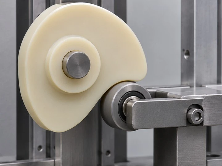
A cam profile is most useful when it is tied to the intended motion. Give the rotation direction and angular reference, the follower type and size, plus the expected sequence of movement and dwell. A section through the installed cam should show the follower position relative to the cam axis. State whether the follower is a roller, sliding member or other defined mechanism. A new follower diameter can change where contact occurs even when the cam drawing itself has not changed.
Mark the working contour separately from recesses, clearance faces and cosmetic geometry. At a loading transition, confirm which region first sees contact and which region must support motion through the next phase. Show any fixed stop or adjacent link that constrains the follower. For inspection, reference the contour to the bore and the orientation feature used in the machine. A report organized around the working cycle can show where a profile or angular position needs attention before the tooling is released.
Illustrative component and assembly detail.
See the custom POM rotary table detent cam for an example of a molded indexing component.
Treat the hub, shaft and retention as an assembly
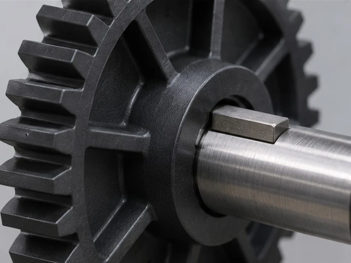
A shaft seat, key, spline or molded-in insert can transfer torque or locate the molded part. Specify which feature performs each function and what provides the axial stop. A tight bore alone tells the buyer little about where the gear face sits relative to its neighbor. Include the end view and section of the mating shaft, plus the fitted spacer, washer, retaining clip or fastener where relevant. If a metal insert is used, identify its drawing and any installation operation included in the quote.
Check the consequences of the selected fit on the molded hub and on the position of the drive component. The installation method and the final fitted state may require different measurements. Identify whether the hub check is made on a free part or after the mating hardware has been installed. If movement or wear has appeared in service, keep photographs of the shaft and hub together. A loose fit at the bracket or a changed running position can produce evidence that otherwise looks like a defect in the gear teeth or cam face.
Illustrative component and assembly detail.
Select a specific grade for the contact pair
POM and nylon grades are considered in many molded drive and wear applications. Start by identifying both contacting surfaces, the intended lubrication arrangement, expected temperature and duty. Nylon moisture conditioning can affect dimensions and should be included in the inspection plan when it is relevant. Reinforcement can change stiffness and molding behavior, and the choice should account for the mating surface and its finish. Use material data for the specified resin in the relevant condition and have the design owner validate the full assembly.
A quiet trial without a representative load tells a limited story about performance in service. Monitor the signs that actually matter to the installation, such as change in position, noise, contact location, or visible wear. If the machine sees cleaning fluids, dust or lubricants, include their identity and exposure conditions in the RFQ. Record whether the material choice is fixed on the drawing or is a candidate for review. Document any resin or mating part change before comparing later trials with the original baseline.
For related interfaces, read our guide to low-friction injection molded wear parts.
Review wall sections, gate and cooling before tool release
Map the thick hub, web, rim and any supporting ribs on a section view. The way those zones fill and cool can affect tooth pattern, cam contour and bore position. A tooling discussion should cover the placement of the gate, parting line, ejection and critical cooling regions. Put each required working surface on the drawing so the proposed tooling witnesses can be checked against real contact conditions. For broad or asymmetrical parts, review the potential for one side or a heavy section to move differently as it cools.
Choose critical tolerances with the equipment team. A tight tolerance can be valuable when it protects shaft alignment or the contour timing that locates a transfer station. Applying the same tolerance to spare material around the rim can add inspection work without improving the mechanical fit. Confirm what the supplier can demonstrate on trial parts and whether the tool will require correction. Keep a clearly marked dimensional record after any tool change so later production parts are evaluated against the accepted revision.
Validate the molded component in the actual drive
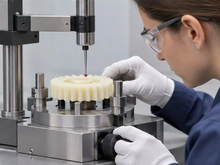
Start with measurements against the released drawing, then assemble a representative gear pair, cam mechanism or coupling using the approved hardware. At the first checks, document the fitted datums, clearances and motion path. Where the machine has several load cases, agree on the representative conditions with its owner before running an approval trial. Record orientation and operating conditions alongside inspection results so the next trial can reproduce the setup.
Check what happens after repeated motion under the planned test conditions. Look at where the contact band has developed and whether the machine still reaches its required position. A visible wear mark can be normal in a contact region or indicate interference elsewhere, depending on the equipment definition. Keep the mating part revision and the mold cavity or lot reference with the result. For a repeat order, record what was accepted and which characteristics will be checked on later deliveries.
Illustrative component and assembly detail.
Send the drawing and the mating interface with the RFQ
Supply the 3D model, a dimensioned 2D drawing, and the expected sample and production quantities. Add the mating gear, shaft or follower drawing and include the operating conditions that govern grade selection. A used component can help explain its mounting arrangement and damage pattern. Mark the worn regions and provide a nominal or unworn reference wherever possible. For several mechanisms in the same machine family, identify the exact combination each version will fit.
A clear quotation package should separate tooling, molded parts, bought-in inserts and any agreed secondary operations. State who will approve fit and who will evaluate the drive in the complete machine. Give inspection and packaging instructions when tooth profiles, cam faces or a particular hub finish need protection during shipment. SWKS can then assess manufacturing feasibility and prepare a quote that follows the intended part revision.
Explore SWKS custom plastic injection parts for industrial assemblies.
Discuss your molding project with SWKS
Send your STEP, STP or IGS drawing, assembly requirements and expected quantity to amanda@tjswks.com or call 0086-15222707659.