


Tianjin SWKS Technology & Development Co.,Ltd is one of the most reliable manufacturers and suppliers of custom pom industrial automated assembly indexing pinion in China. If you're going to buy bulk cheap custom pom industrial automated assembly indexing pinion, welcome to get quotation from our factory. Quality products and low price are available.
Custom POM Industrial Automated Assembly Indexing Pinion
SWKS offers made to drawing injection molding for the indexing pinion. Send the operating envelope and assembly references with your CAD model so the proposed material grade, molding features and acceptance checks can be reviewed for the intended industrial equipment.
Indexing Motion Through a Small Pinion
An indexing pinion translates drive motion into repeatable movement in an automated assembly station. It may mesh with a rack, ring or another gear selected by the machine designer. This POM part is supplied to the geometry and interface defined for that mechanism. The purchase request should identify the moving member, direction of travel and increments commanded during the working cycle. Note whether the pinion reverses or returns without load after completing a stroke.
The initial design discussion can focus on the position the machine must achieve and how the drive establishes it. Lost motion, shaft deflection and accumulated fit clearances all contribute to the assembled result. Provide the drive layout and identify which features carry angular registration. If the pinion is a replaceable spare, compare the released component drawing with the installed mechanism revision. A small outline change at a hub or shaft stop can alter tooth engagement without changing the basic tooth count.
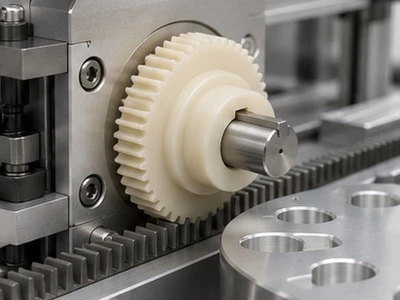
Illustrative rendering. Supplied geometry and dimensions follow the approved customer drawing.
Defining the Working Tooth System
A pinion drawing should state the tooth system and the parameters that define its mating geometry. Module or diametral pitch, pressure angle, tooth count, working face width and profile details belong to the controlled specification where applicable. The mating rack or gear drawing is particularly useful because it identifies the tooth form and how the pair sits in the machine. Give the center distance or rack offset used during the qualification trial.
Backlash and running contact should be evaluated at the positions relevant to indexing. Check around a full pinion rotation if the drive uses more than one engagement region. A good check at one tooth can miss an angular area that runs tightly. Specify the acceptable relationship with the mating member and the conditioning or temperature used during measurement. A buyer may define a fitted functional check in addition to component dimensions when motion repeatability depends on several assembled interfaces.
Angular Reference From the Shaft to the Station
A shaped bore, key or flat can register the pinion to its shaft. The drawing should identify the angular relationship between that interface and a tooth or other reference when the machine uses it for timing. Include any hardware that establishes axial location. A hub can be concentric and still sit at a different tooth face position if a spacer or shaft shoulder changes. Use an assembly section to show the working stack.
Where assembly staff need to distinguish orientations, the designer can provide a visual or molded feature in an area clear of the mesh. Confirm its location before tool design. If a separate metal insert is part of the torque path, identify its drawing and accepted installation method. The quotation should state whether it includes molding around an insert, installing a purchased item or supplying only the plastic pinion. Those routes can require different inspection references.
| Project item | Information for review |
|---|---|
| Material | POM grade subject to application approval |
| Process | Custom injection molding |
| Key drawing features | tooth geometry, angular reference and hub register |
| Mating assembly | the mating rack or gear, pinion shaft and drive housing |
| Drawing formats | STP, STEP and IGS |
| Dimensions and operating limits | As specified on the approved drawing and qualification plan |
POM Grade and Motion Duty
The proposed acetal grade should be considered with loading frequency, peak torque, speed and any lubrication arrangement. The contact pair includes the material and finish of the mating rack or gear. A modified wear formulation changes more than the family name on the drawing. If a material replacement is proposed, use the customer's agreed duty and acceptance measures to compare it against the original. State whether grade selection is fixed or open for a sampling review.
A stalled or jammed assembly sequence can be a distinct condition from normal index travel. The machine designer determines the drive limits and how the cell responds. Include the duty conditions that the component is required to withstand in the approved specification. Surrounding heat, dust, cleaning fluids and idle periods can be relevant to that review. Describe them at the location of the pinion so the material discussion reflects the actual drive environment.

Illustrative rendering. Supplied geometry and dimensions follow the approved customer drawing.
Tooling a Small Pinion With Measurable References
The bore, tooth band and hub faces need references that can be carried from tool review to sample inspection. A molded split line or gate witness can affect fit if it enters a working region. Reserve suitable areas for these tooling features and show which faces establish the inspection datum. A thick hub joined to a narrow rim can require attention during cooling and shrinkage review. The designer can approve any proposed section change using the mating assembly model.
Compare first articles across cavities using a consistent method. A dimensional check can be paired with the agreed master rack or gear where appropriate. Record the master identity and the positions used in the check. If a later cavity adjustment shifts the tooth relationship or hub register, retain the revised drawing and new report together. This gives repeat orders a clear accepted reference for the indexing pinion used in that station.
A Position Check Tied to the Assembly Cycle
An indexing station can be evaluated by recording where the driven member arrives after each commanded move. Identify whether that arrival is measured at the rack, at the next fixture or at a separate sensor. The check should distinguish a stop reached from one direction from a stop reached after reversal. A small angular gap at the pinion can produce a measurable travel difference at another point in the mechanism. The machine designer can name the reference points and the sequence that represents its acceptance case.
During a trial keep the reference rack and its mounting condition identified. A fresh rack, a worn rack and one adjusted after a service call can place contact on different parts of a tooth flank. Photograph the full fitted mesh at the beginning of the test. Retain readings at the chosen stations and specify which load was present. The report can connect those observations to the pinion cavity and material lot instead of relying on the assumption that every installation in the machine family behaves the same way.
Controlling Pinion Versions at a Changeover
Assembly lines may use similar pinions at neighboring stations. One wheel may differ by a bore flat, tooth count or hub projection that is difficult to recognize from an oblique photograph. List the station identifier and buyer part number on each purchase line. Where an orientation mark is allowed, show it on a nonworking face in the drawing. Provide the marking content and distinguish it from a cavity or date code used by the molding supplier.
For a proposed tooling program, share the estimated demand for each variant and the sequence in which samples are needed. The supplier can review whether the versions require independent molds or an agreed insert arrangement. Keep the drawings separate where a change affects the mesh. The customer approves which variants can share a sampling report and which need their own position trial. Review the associated rack and shaft combinations before describing a component as an alternative for another station.
Sample Delivery and Acceptance of the Index Drive
A first article package can carry the molded pinions in protected positions, with the measured samples individually identified. Teeth and hub stops can be protected from contact during transport. The buyer can state whether a separate set is needed for installation and another for retained dimensional references. Distinguish normal cosmetic witness marks from the faces covered by the acceptance criteria. Label each accepted sample with its station, part revision and trial record reference.
The production quotation can state the resin designation, molding quantity and inspection scope for repeat deliveries. A signed print or controlled approval document establishes the part revision to manufacture. If a later drive improvement changes the rack offset or commanded sequence, the machine owner can identify which previously accepted checks should be repeated. Send the component and mating CAD models, a dimensioned gear print and the relevant indexing duty with the inquiry so the proposed tooling is reviewed against a defined motion requirement.
Installation Notes From the Equipment Owner
Document access to the shaft stop, the retention method and any adjustment included in the approved setup. These details help a service team install replacement pinions in the same position used for qualification. A field observation should state whether other gears, rack supports or sensing positions changed at the same time. The released part drawing remains the reference for the molding supplier, while the equipment owner manages the installed drive settings and approval of its operation.
Request a Custom Molding Quotation
Explore our plastic injection parts and engineering plastics selection guide for related applications. Email your drawing, required grade and quantity to amanda@tjswks.com or call 0086-15222707659.
Hot Tags: custom pom industrial automated assembly indexing pinion, China, suppliers, manufacturers, factory, bulk, cheap, low price, quotation, Low Quantity Injection Molding, PA66 Plastic Special-shaped Parts Injection Molding Parts, packaging plastic injection parts, Plastic Injection Conduit Molding Machine Parts, tpe plastic product list, transparent plastic injection parts


