


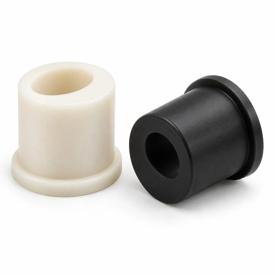
Tianjin SWKS Technology & Development Co.,Ltd is one of the most reliable manufacturers and suppliers of custom pom eccentric adjustment bushings in China. If you're going to buy bulk cheap custom pom eccentric adjustment bushings, welcome to get quotation from our factory. Quality products and low price are available.
Custom POM Eccentric Adjustment Bushings
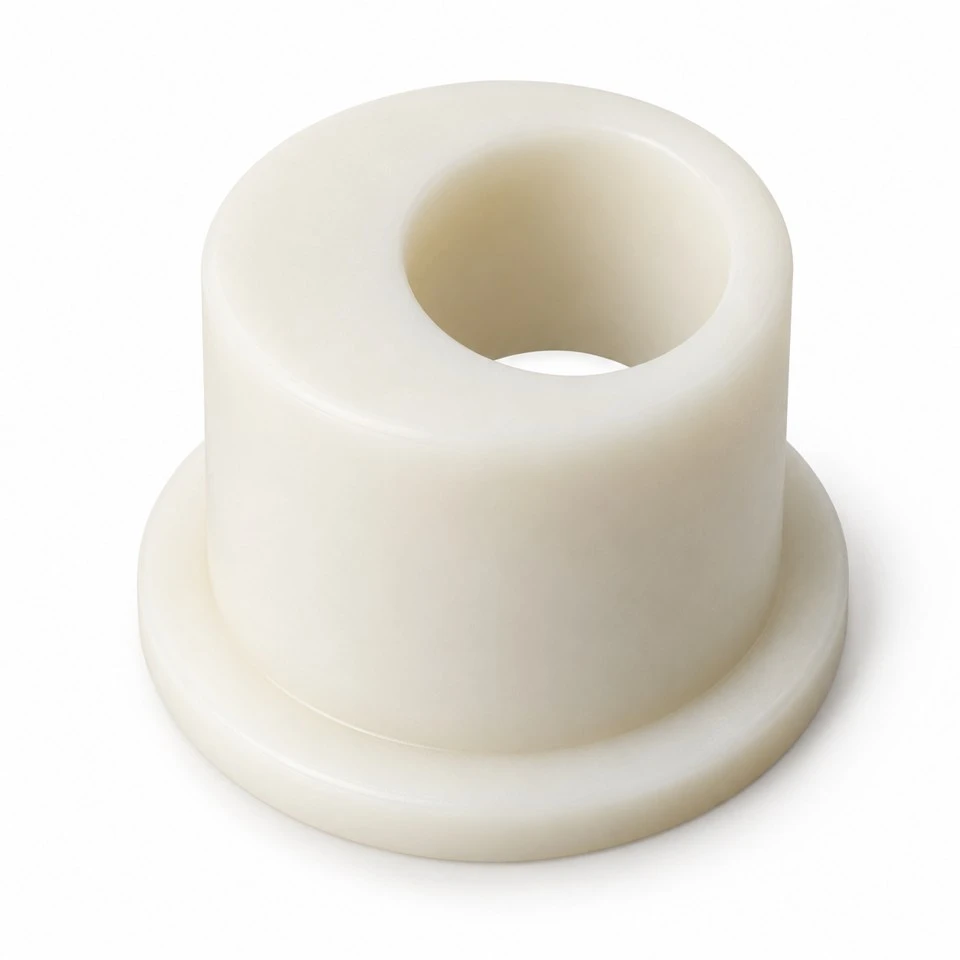
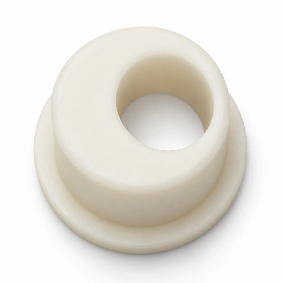
A small change in shaft position can determine whether an industrial guide runs with the intended clearance. SWKS develops custom injection molded POM eccentric adjustment bushings for assemblies that use an offset bore to set that position. The illustrated flanged sleeve combines a circular locating barrel with a deliberately displaced axial hole. Final dimensions follow the customer drawing and the complete mating arrangement. Send your design and quantity requirements to amanda@tjswks.com for review.
Material: ABS/POM/PA66/PP/PC/PA/PU/TPE/TPU etc.
Processing Service: Injection
Drawing: STP/STEP/IGS
Contact: amanda@tjswks.com / 0086-15222707659
How does an eccentric bushing change a component position?
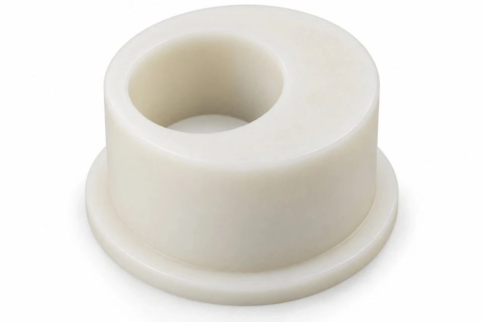
The bore axis is displaced from the outside cylinder axis. When the bushing turns in a locating pocket, a pin or shaft supported in the bore moves around that outside axis. This provides a compact way to adjust a position without translating the complete mounting block. The designer determines the useful adjustment direction and range from the surrounding assembly. The circular motion also produces a second movement component that must be considered.
A complete revolution returns the bore to its starting position. Over a selected portion of rotation, the mechanism may provide the movement needed to set a roller gap or align a locating pin. The bushing does not generate straight-line travel on its own. Include the complete arrangement when requesting a part so that the offset, permitted rotation and surrounding clearances can be assessed together rather than treated as independent dimensions.
Which dimensions define the required eccentricity?
Specify the outside locating diameter, bore diameter and the distance between their axes. A drawing that lists only two diameters does not define an eccentric bushing. Show the offset directly, together with its tolerance and the datums used for inspection. If the design begins from a desired adjustment range, supply the mechanism geometry and useful angular sector so the engineering review can connect that range with the proposed offset.
The thinnest wall follows from the outside diameter, bore size and offset. Review this region explicitly, including transitions into the flange. Increasing eccentricity within the same envelope reduces the material available on one side. A nominal adjustment target therefore needs to be balanced with molding feasibility and the mechanical interface. Do not assume a larger offset can be substituted without checking the wall, load and retained fit.
Where can a custom POM eccentric sleeve be used?
Possible applications include position setting for guide rollers, adjustment of lightly loaded locating pins and alignment features in small industrial fixtures. Suitability depends on the actual force, movement and retention arrangement. The bushing may be stationary after adjustment or may move during service; these are different duties. State which function is intended instead of describing the component only as an adjustable bearing.
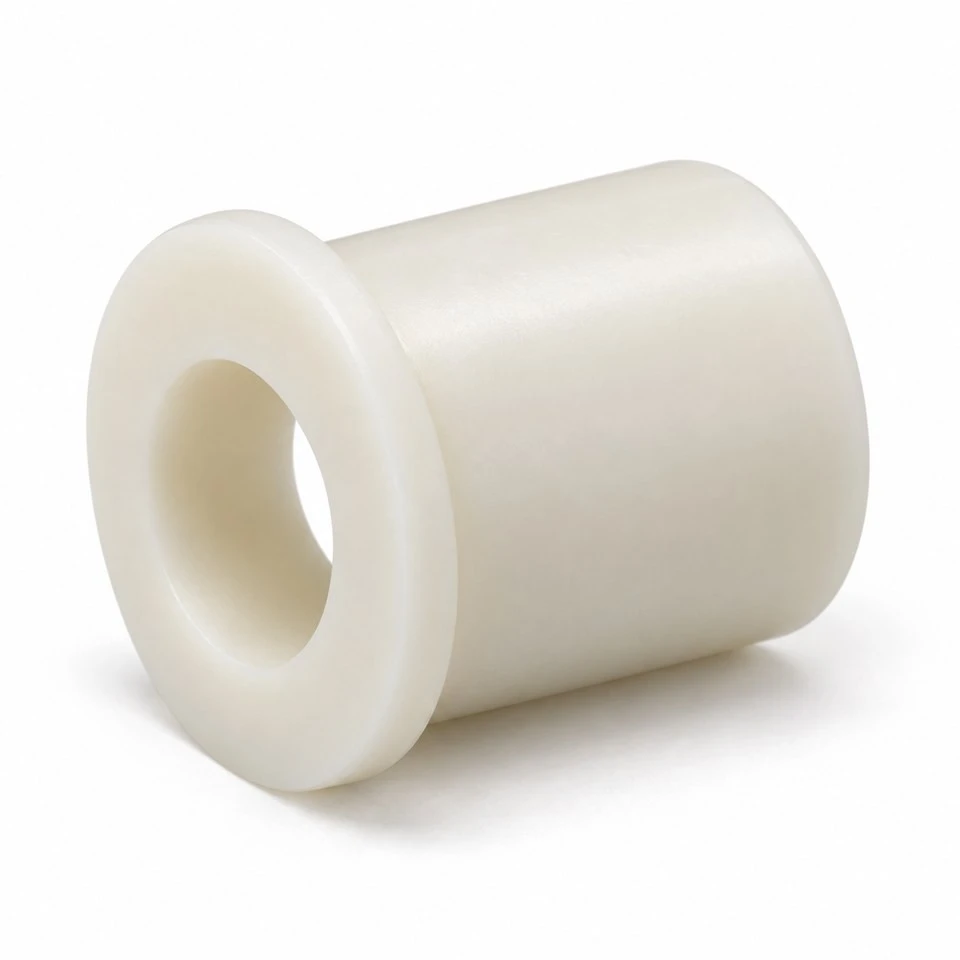
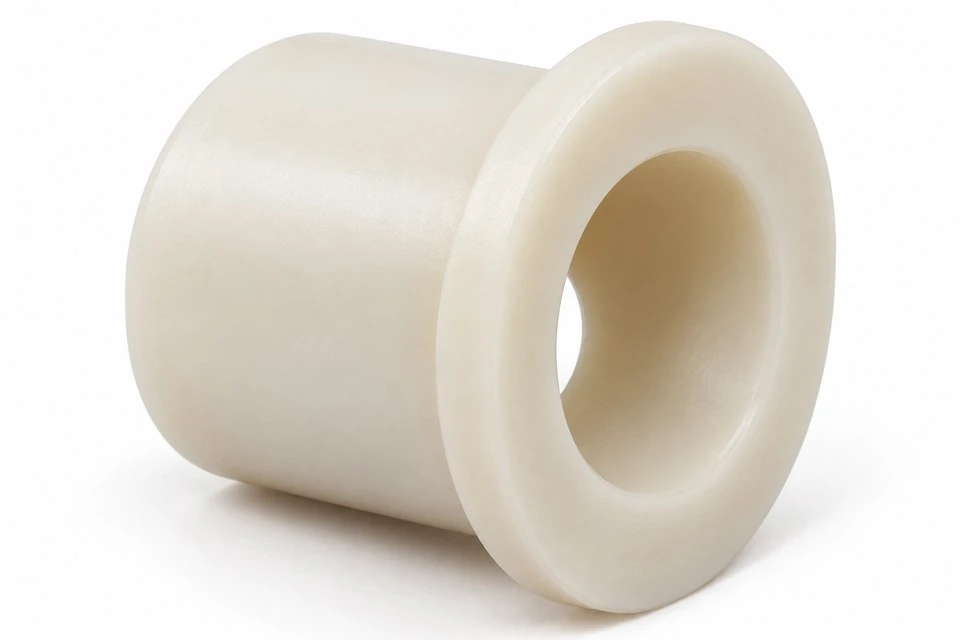
The illustrated part is a flanged cylindrical design with a plain eccentric through bore. It is a custom concept rather than an approved replacement for a named machine. The images do not establish a load rating, speed limit or service life. If a metal shaft rotates continuously inside the bore, provide that duty for separate review. A position-setting component should not automatically be treated as a qualified continuous-running bearing.
How should the outside cylinder fit the mounting pocket?
Identify the housing material, pocket dimensions, surface condition and assembly temperature. The outside interface must allow the agreed adjustment procedure while maintaining the required location. A loose pocket may introduce movement beyond the intended eccentric setting. An overly tight fit may make adjustment difficult or distort the sleeve. The fit should be defined with the mating drawing and representative samples rather than selected from the bushing diameter alone.
Describe whether the bushing is installed by hand, with a fixture or by another controlled method. Include any split housing or clamp that changes its outside shape when tightened. Where the pocket has a shoulder, show its contact with the flange and the clearance at the barrel end. The locating cylinder, seating face and clamping arrangement should work as a coordinated interface throughout the required adjustment sector.
What prevents the setting from changing after adjustment?
An eccentric bushing needs an agreed means of retaining its selected angular position. The concept images do not include a locking system. A surrounding clamp, controlled axial retention or another specified feature may be used in the assembly, depending on the application. Provide that arrangement and explain how it is released and retightened. The bushing should not be assumed to hold a setting solely because its outside surface feels snug.
Show the direction of the operating force relative to the offset bore. That force can create a tendency to rotate the eccentric part. Define the permitted movement after locking and any repeated adjustment requirement. If a screw contacts the plastic directly, review the contact area and possible local deformation. The final retention method and tightening instructions belong to the equipment specification and should be validated using the intended hardware.
How does the flange establish the axial position?
A flange can provide an axial seating face and help separate the moving or located component from the housing surface. Supply its diameter, thickness and required relationship to the barrel and bore. Indicate whether it simply limits insertion or carries an axial load. Those functions can lead to different requirements for contact area, flatness and the transition between the flange and the cylindrical body.
Leave enough clearance around the flange for the planned adjustment method. A neighboring plate or fastener can prevent rotation even when the barrel fits correctly. Include the full stack of mating components and washers if these determine the installed height. The barrel should not bottom unexpectedly before the flange seats unless the assembly specifically requires that condition. Dimension the intended locating relationship rather than relying on the appearance of a sample.
Which shaft details affect the eccentric bore?
Provide the mating pin or shaft diameter, material, finish and permitted variation. State whether the shaft is fixed in the bore, slides during setup or rotates during operation. The same nominal bore size can serve different functions only with an appropriate fit and validation. If the shaft has a shoulder or chamfer, show how it approaches the bore entrance and whether it contacts the flange face.
Identify lubrication, contamination and temperature conditions where they affect the interface. POM should not be described as universally maintenance free for every shaft pairing and duty. A static locating pin and a rotating steel shaft impose different requirements on wear and clearance. If functional testing is needed, define the speed, force, cycle and acceptance criteria with the actual mating material. Keep those criteria separate from basic dimensional inspection.
Why specify the complete POM grade before tooling?
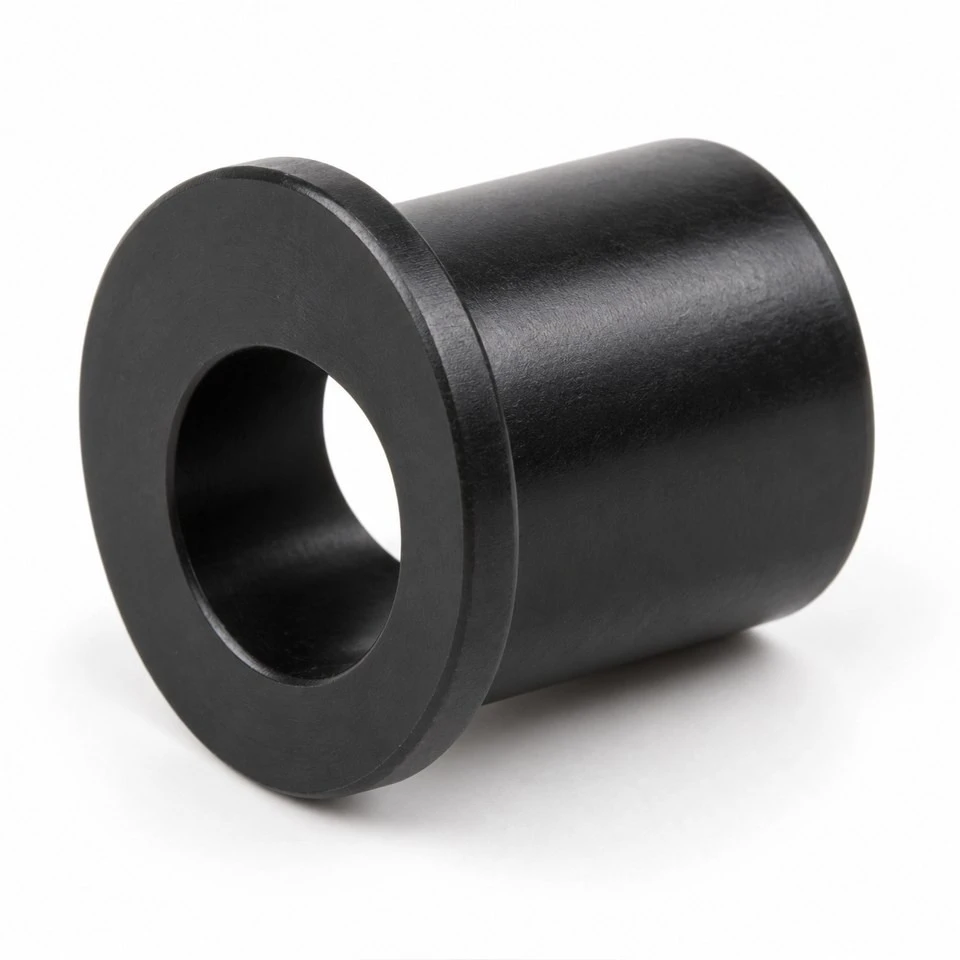
Acetal grades differ, and the selected formulation needs to match the operating environment and mechanical requirements. State the full resin designation where it is already approved. Otherwise provide the information required for material review, including temperature, chemicals, cleaning exposure and any dimensional stability priorities. Natural and black illustrations show possible appearances; neither identifies a specific formulation or certifies the performance of the finished assembly.
If virgin resin, traceability or a particular compliance document is required, include that in the purchasing specification. Do not infer those requirements from the generic material name. A proposed grade change should be reviewed against the approved fit and functional checks. Colorant and other formulation changes may also require agreement. Material identity, drawing revision and sample approval should remain connected when repeat production is ordered.
Can the offset bore be made directly in the mold?
The plain axial geometry can be considered for injection molding with an offset core, subject to detailed tool review. The unequal wall around the bore influences cooling and shrinkage, so the molded shape must be assessed beyond a simple two-dimensional outline. The flange transition and thick side of the barrel need attention. The tool design should consider filling, core support, ejection and the surfaces used to locate the part.
Some applications may need a secondary operation to meet a particular bore or location requirement. This should be agreed from the drawing rather than assumed to be included or unnecessary. Mark where gate and ejector vestiges are acceptable, especially around the outer locating cylinder and flange seating face. Define any required edge break at the bore entrances without allowing uncontrolled trimming to alter a functional diameter.
How should offset and fit be checked on initial samples?
Use a defined datum system and measurement method for the outside axis, bore axis and flange face. The offset is a relationship between features, so separate diameter measurements alone cannot verify it. Where a fixture is used, describe how the bushing is supported without forcing it into a distorted shape. Record the inspection condition and any required interval after molding before measurements are accepted.
Functional approval should also check adjustment through the intended angular sector in a representative housing. Install the specified shaft and locking hardware, set the required position and verify retention by the agreed method. This can reveal interference or assembly behavior that individual dimensions do not capture. If the sample is approved with a modified housing, update the mating information so the result does not become disconnected from the production assembly.
What information is needed to quote a repeatable custom part?
Send an STP, STEP or IGS model and a dimensioned drawing with the outside diameter, bore, eccentricity, barrel length and flange details. Include the housing and shaft interfaces, adjustment direction, load, retention method and working environment. State the required POM grade and color, first quantity and expected annual demand. If a physical sample is the starting point, identify the dimensions that are critical and the changes required.
For repeat orders, confirm whether the housing, shaft or locking arrangement has changed since sample approval. Similar-looking bushings with different offsets should have distinct part numbers and packaging identification. Packaging should protect the locating surfaces and keep debris out of the bore. Agree inspection records, labeling and delivery requirements before production. A controlled drawing and clear assembly reference help repeat batches reproduce the approved setting behavior.
Contact amanda@tjswks.com to discuss a custom POM eccentric adjustment bushing for your equipment.
Hot Tags: custom pom eccentric adjustment bushings, China, suppliers, manufacturers, factory, bulk, cheap, low price, quotation, pom aerospace parts, pom baffle parts, pom enclosures, pom food processing parts, pom supports, pom threading parts


