


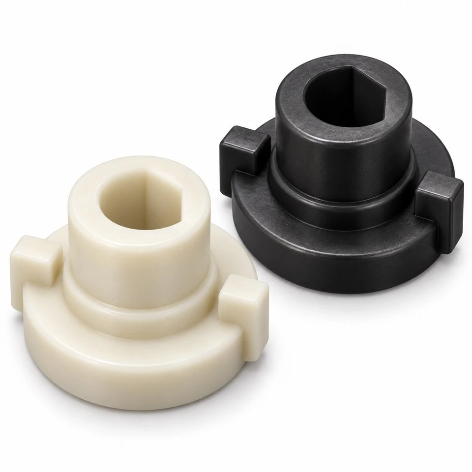
Tianjin SWKS Technology & Development Co.,Ltd is one of the most reliable manufacturers and suppliers of custom pom valve actuator shaft couplings in China. If you're going to buy bulk cheap custom pom valve actuator shaft couplings, welcome to get quotation from our factory. Quality products and low price are available.
Custom POM Valve Actuator Shaft Couplings
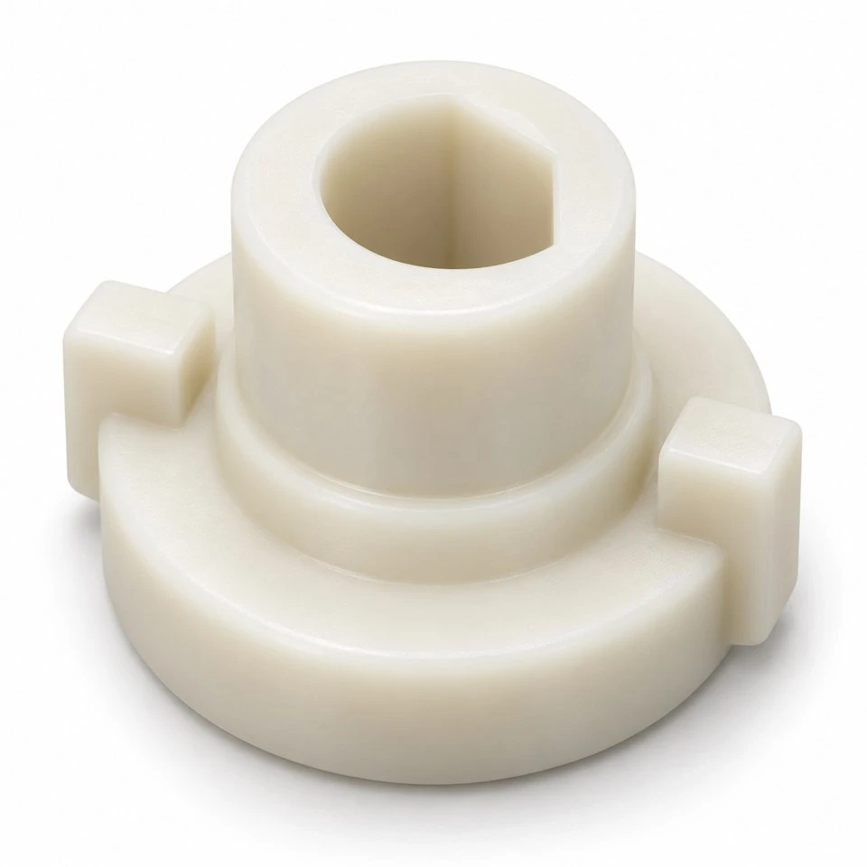
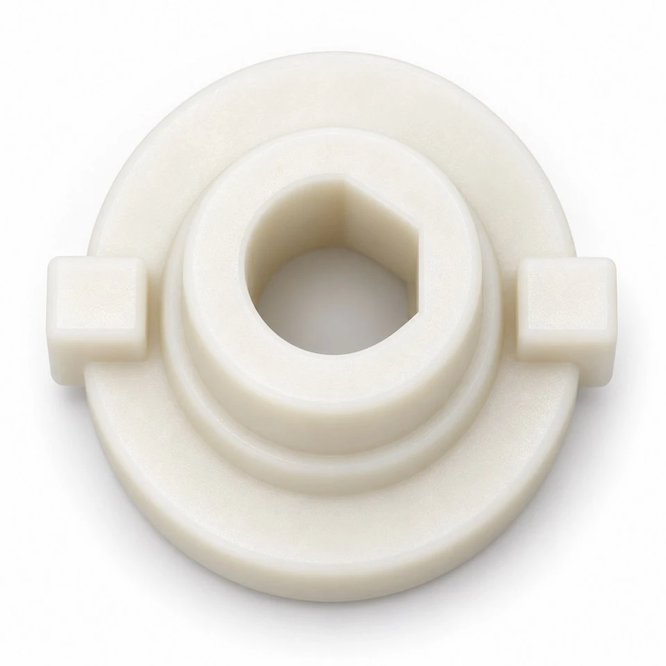
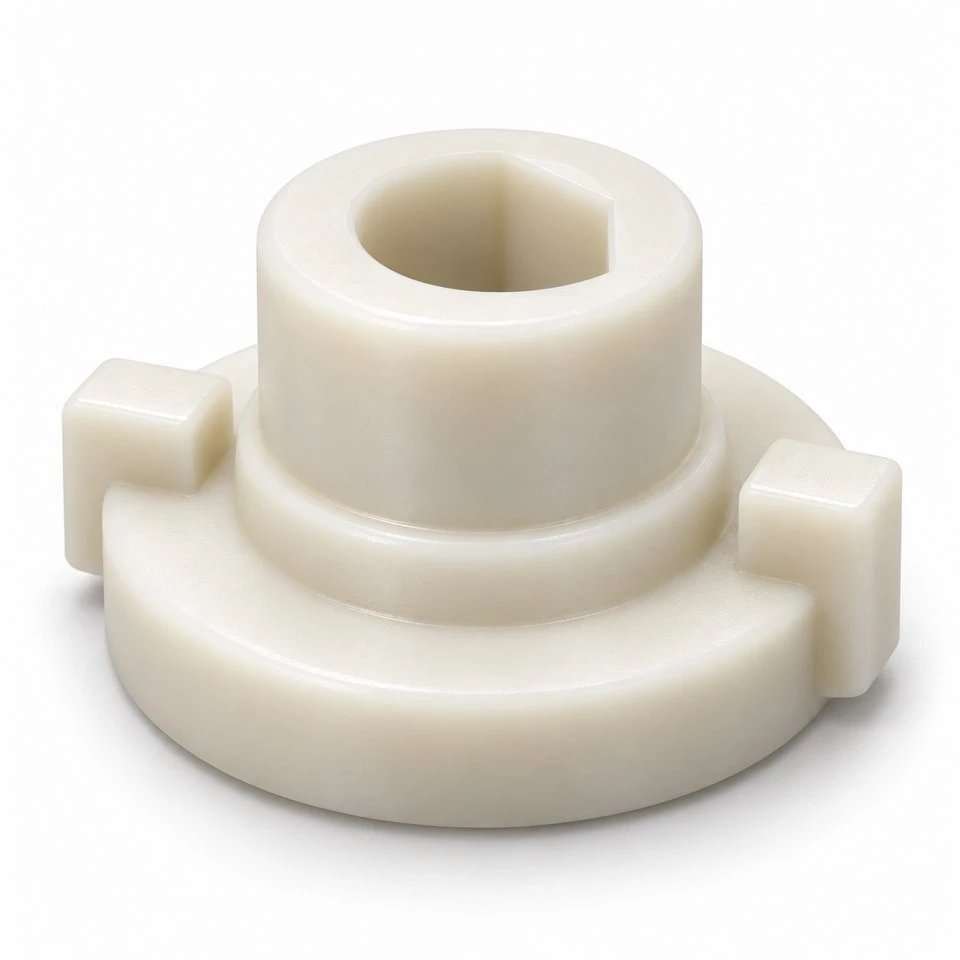
A small coupling insert can determine whether a valve operator feels positive, develops lost motion, or loads the stem unevenly. SWKS offers custom molding for acetal shaft adapters that connect an actuator output to a valve stem within a defined assembly envelope. The part is developed around the two mating interfaces rather than selected from a universal coupling catalogue. Send the stem profile, actuator socket and expected operating conditions to amanda@tjswks.com for a project review.
Material: ABS/POM/PA66/PP/PC/PA/PU/TPE/TPU etc.
Processing Service: Injection
Drawing: STP/STEP/IGS
Contact: amanda@tjswks.com / 0086-15222707659
Where does this adapter sit in a valve assembly?
The coupling occupies the short space between a driving output and a driven spindle. One end receives the stem; the other engages the operator. A D socket, double flat, square recess or external drive lug can establish angular engagement. A shoulder may control insertion depth while an outer flange gives the assembler a seating reference. These details belong to a customer-specific interface, so an attractive outside shape alone cannot establish compatibility.
Typical project discussions concern compact instrument valves, small rotary controls and equipment mechanisms with intermittent angular movement. The proposed polymer component must be assessed against the actual duty. It is not automatically appropriate for every valve size, emergency function or continuously loaded drive. The coupling transfers motion; it does not by itself provide a fluid seal, a pressure boundary or a certified safety function. Those responsibilities remain with the complete valve design.
Which dimensions establish the two mating interfaces?
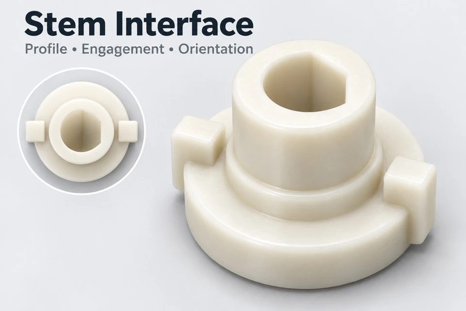
Begin with a cross section through the assembled stem and actuator output. Record the stem width across flats, maximum corner radius, engagement depth and axial clearance. For a D profile, specify the circular diameter and the distance from the flat to the opposite arc separately. Describing a socket only by its nominal diameter leaves the flat position undefined and can produce a part that slides onto the spindle but does not drive it as intended.
At the output side, locate each lug or external flat relative to the stem socket. Angular orientation matters when the actuator has a defined closed position. Also identify the reference face used to measure overall height. A flange underside, hub end or socket bottom can each be a useful datum, but they are not interchangeable. A sectioned drawing should make clear which face seats first and which faces must remain clear throughout operation.
How should operating torque be described?
Breakaway torque, running torque and end-stop torque describe different events. A valve may require a brief initial effort after standing idle, then turn with much less resistance. An actuator can also apply torque after the valve has reached its stop. Providing only the average running value hides these peaks. State the direction of rotation, frequency of reversals, operating angle and whether the motor current or another feature limits the maximum output.
Include abnormal conditions that the assembly is expected to survive, such as a temporarily sticking stem or repeated commands against a stop. Whether these conditions require uninterrupted operation, harmless slip or controlled replacement is a design decision. No universal torque rating is assigned to the illustrated adapter. Capacity depends on socket wall thickness, lug root geometry, engagement length, grade, temperature and the complete load path, and needs confirmation on representative assembled samples.
Why consider acetal for a compact rotary adapter?
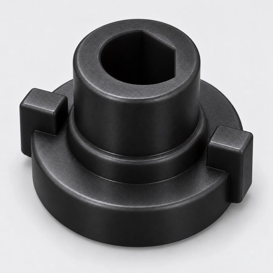
POM is an engineering thermoplastic often considered where a molded component needs a firm shape and smooth mating surfaces. A compact adapter can combine a stem recess, seating shoulder and actuator engagement features in one molding. That arrangement can simplify handling during assembly, provided the features can be formed and released reliably. The choice between available acetal grades should follow the environment and mechanical demand rather than the appearance of a white or black sample.
Grade selection also requires disclosure of cleaning agents, oils, nearby heat sources and storage conditions. If the adapter sits close to a hot valve body, the local polymer temperature can differ from room temperature. Long periods under torque raise a different concern from a brief hand-operated movement. We therefore discuss the material against the customer's duty cycle and approved specification instead of promising a generic temperature range, chemical resistance level or service life.
How can backlash be controlled without making assembly difficult?
Clearance between the socket and stem allows the part to be installed, but excessive clearance creates angular movement before torque reaches the valve. An overly tight recess can cause high insertion force or prevent full seating. These competing needs should be evaluated together. Define the acceptable free angle at the actuator, the permitted installation force and whether the coupling must be removable during maintenance. A fit specification is more useful when it includes those functional outcomes.
A short lead-in can help the socket find the stem, while adequate straight engagement preserves the driving contact. The lead-in must not consume so much depth that the effective engagement becomes too short. If the metal stem has a chamfer or rounded tip, include it in the assembly model. Measuring only the nominal socket depth can overstate the length actually transmitting torque, especially in a very shallow adapter.
What prevents the coupling from being loaded sideways?
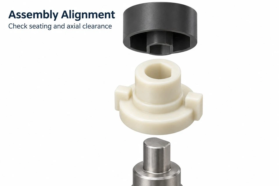
A rigid polymer insert should not be assumed to correct significant shaft misalignment. If the actuator output and stem axes are offset, the socket may bear on one edge and the flange may rub against adjacent hardware. Check the mounting bracket, bearing locations and positional tolerances before assigning the entire accommodation to the coupling. The assembly should establish alignment through suitable locating features rather than relying on the insert to force the shafts into position.
Axial movement deserves a separate review. A stem that rises, floats or shifts during operation can push against the socket bottom. The resulting thrust may affect the actuator or valve. Specify the necessary end clearance and identify any retaining element. Where a flange is used only as an assembly stop, its role should be distinguished from a thrust-bearing surface. This avoids accidentally treating a convenient shoulder as a continuously loaded bearing.
Which molded features deserve an early tooling review?
The socket profile and external drive ears govern how the mold opens. Features aligned with the main opening direction may be straightforward, while transverse recesses or enclosed side holes can require additional mold actions. A tiny retaining undercut can change tooling more than a much larger open flange. Review these features before the drawing is frozen, especially when retention can instead be achieved by a neighboring component in the actuator assembly.
Lug roots should be discussed in relation to both torque and molding. Abrupt section changes can concentrate stress and create uneven cooling. Generous transitions may help, but any radius must clear the mating slot. Gate position, parting line and ejector contact should avoid the functional socket faces where possible. The review should also identify which visible surfaces are merely cosmetic and which establish contact, because the inspection priorities are different.
How is a first sample evaluated meaningfully?
A dimensional report starts with the agreed drawing datums, then checks the socket, drive features, seating height and orientation. Profile gauges or mating fixtures can complement individual measurements when the interface is difficult to describe with a single caliper reading. The gauge definition should be agreed in advance. A part passing one customer's loose reference sample is not necessarily evidence that it meets a fully specified production fit.
Functional evaluation should use the real stem and output socket or representative controlled fixtures. Observe insertion, full seating, free angle, rotation in both directions and removal after cycling. Where torque testing is needed, define the loading rate, holding time and acceptance condition before comparing results. A test to visible failure and a test to permanent angular deformation answer different questions. Record any whitening, cracking, rounded flats or residual looseness rather than reporting only that the part still turns.
What should a purchasing enquiry contain?
Provide the coupling model together with a dimensioned section showing both mating components. Indicate the trial quantity, expected repeat quantities, preferred color and whether a specific POM grade is mandatory. Mark the critical interface tolerances and explain how the assembly is inspected at your facility. If the current adapter has failed, photographs of the contact marks and a description of the operating event are more informative than an unsupported request for a stronger version.
For replacement projects, confirm that the supplied sample represents the intended design rather than a worn condition. A rounded stem socket can enlarge during use, while a distorted flange can hide the original seating height. Reverse engineering should distinguish wear from the required nominal geometry. Quotation scope can then identify tooling, trial samples and production parts clearly, with delivery and price established after the interface and manufacturing requirements are reviewed.
Can the same tool cover different stem profiles?
Some projects use the same outer drive geometry across several stem sizes. Replaceable mold inserts may be considered for that family, but feasibility depends on wall thickness, cooling and the location of each profile. Changing the recess can also change shrinkage and the local load path. Each version therefore needs its own identification and approval rather than assuming that a previously tested size validates every variant. Keep separate drawings for each mating combination.
Discuss how variants will be distinguished at assembly and in packaging. Color can help only if the grade and colorant combination is approved and the operator can reliably tell the colors apart. A molded identification feature is another option, subject to the drawing. The catalogue images are concept illustrations of the coupling form; final geometry, appearance and acceptance criteria follow the approved customer documents. Contact amanda@tjswks.com with your drawings, material requirements and quantities to start the review.
Hot Tags: custom pom valve actuator shaft couplings, China, suppliers, manufacturers, factory, bulk, cheap, low price, quotation, pom automotive parts, pom divider parts, pom grinding parts, pom packaging parts, pom threading parts, pom wheels


