


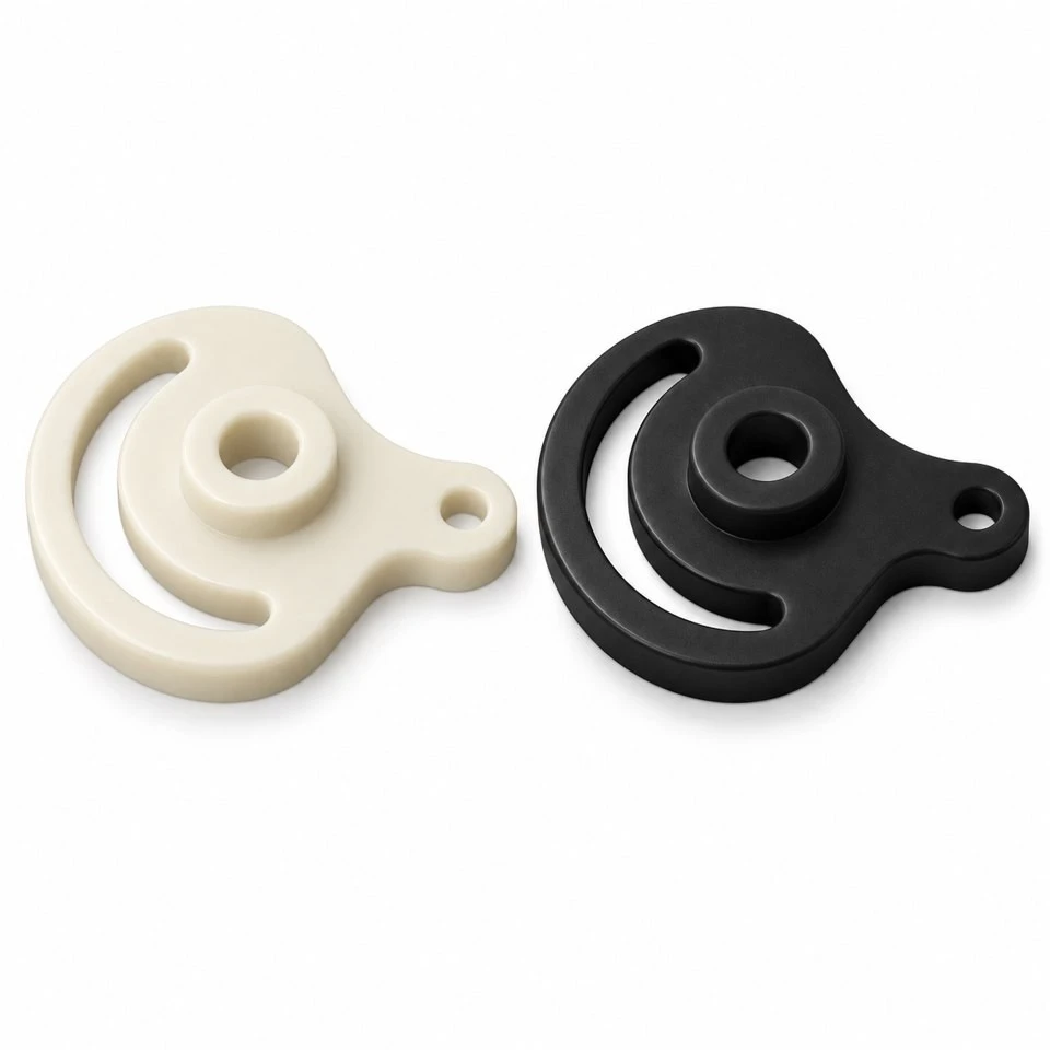
Tianjin SWKS Technology & Development Co.,Ltd is one of the most reliable manufacturers and suppliers of custom pom slotted cam plates in China. If you're going to buy bulk cheap custom pom slotted cam plates, welcome to get quotation from our factory. Quality products and low price are available.
Custom POM Slotted Cam Plates
A shaped slot can turn a short rotary movement into a controlled movement elsewhere in a machine. Getting that movement right involves more than drawing a curved opening in a plate. The pivot, follower and adjoining linkage must work together through the entire stroke. SWKS offers custom injection molding for acetal cam plates developed from customer motion geometry. Share the mechanism layout with amanda@tjswks.com to discuss the molded component and its functional interfaces.
Material: ABS/POM/PA66/PP/PC/PA/PU/TPE/TPU etc.
Processing Service: Injection
Drawing: STP/STEP/IGS
Contact: amanda@tjswks.com / 0086-15222707659
What does a slotted cam plate do?
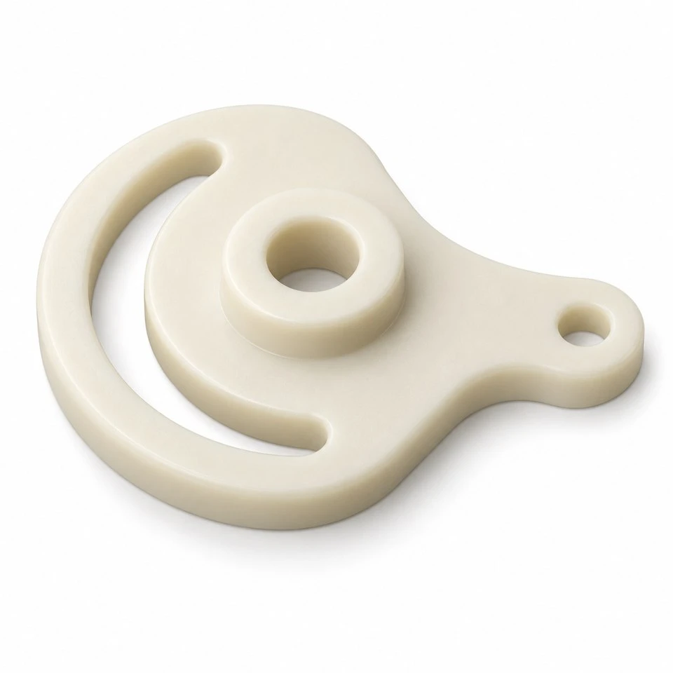
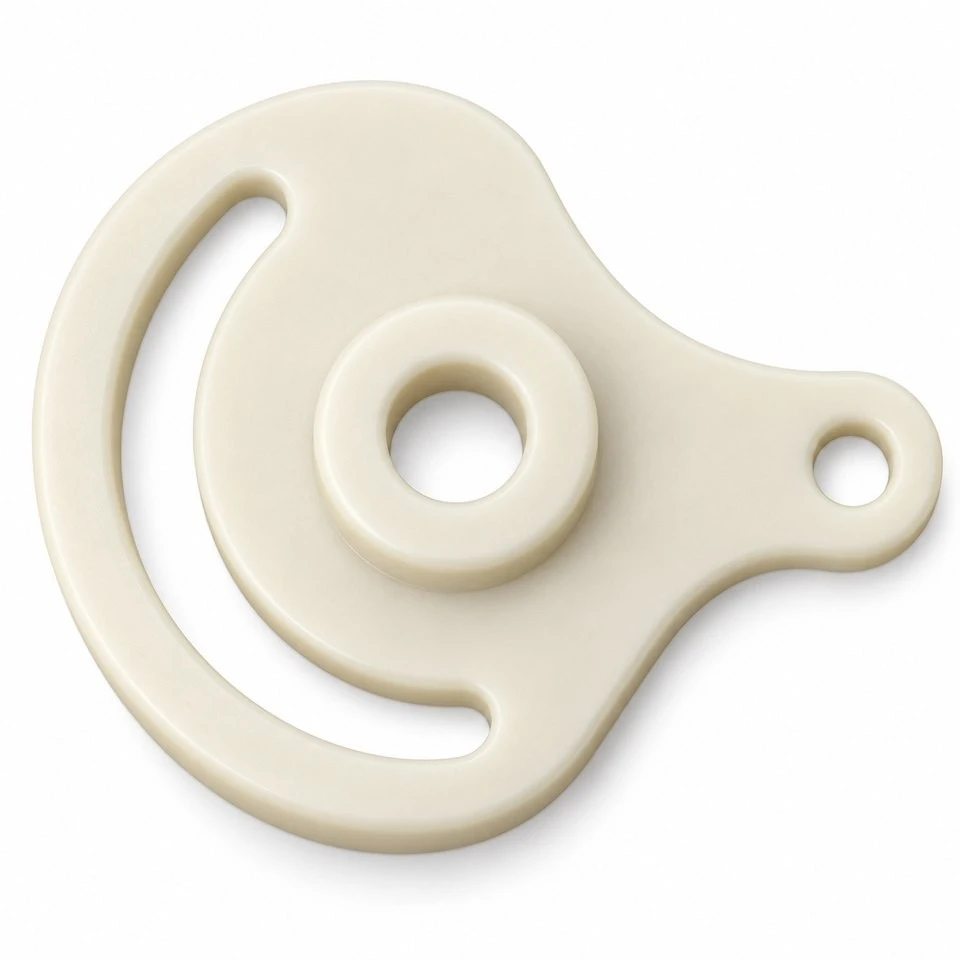
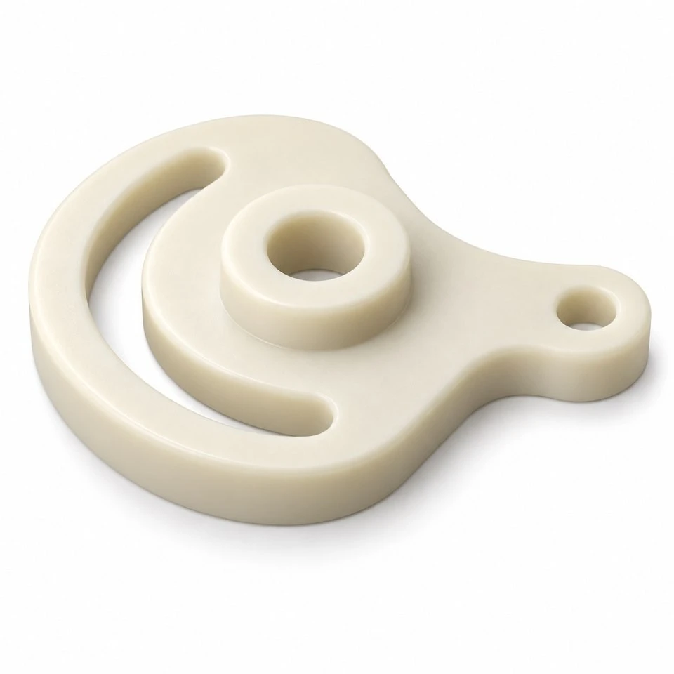
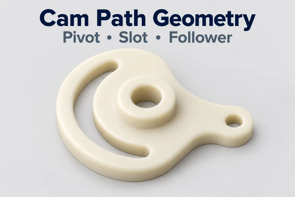
The plate carries a defined path that guides a mating pin or roller as the mechanism moves. Its shape can coordinate a lever, reposition a small component or sequence an equipment operation. Unlike a simple circular wheel, the useful geometry is the relationship between the pivot axis and the path followed by the mating element. A custom plate can place that relationship within the available machine space while incorporating attachment or locating features.
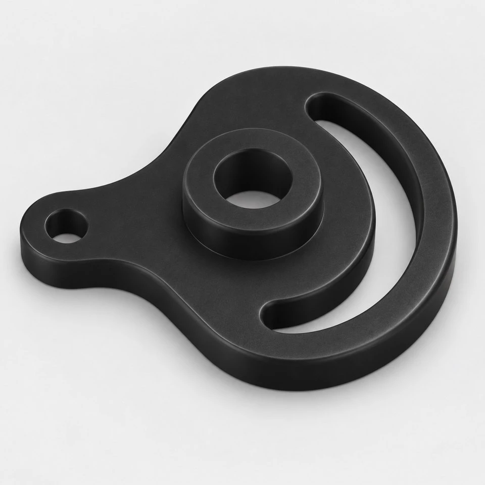
The illustrated component is a concept for a molded cam, not a complete motion system. Bearings, follower pins, return springs and drive parts are separate items unless specifically included in an agreed scope. The illustrations do not specify a load capacity, running speed or service life. Those values depend on the mechanism and material selection and should be confirmed through a defined engineering review and representative trials.
How should the required motion be communicated?
Provide the starting position, finishing position and movement between them. A model showing only the final cam shape can leave the intended function unclear. A sequence of assembly positions or a simple displacement-versus-angle description helps explain why the slot follows its particular route. Identify any dwell, slow movement region or change in direction that matters to the process. The molding discussion can then preserve the important geometry instead of treating the slot as a decorative cutout.
Define the reference used for the input angle and the direction of rotation. For mechanisms that reverse, show the return movement as well as the working stroke. State whether the follower is constrained elsewhere or depends entirely on the slot for its position. This distinction changes how clearance is experienced. A pin supported in a separate sliding guide behaves differently from a loosely supported pin attached to a flexible arm.
Which slot dimensions control the follower fit?
The nominal path and the clear width should be specified separately. The path establishes where the follower center travels, while the width allows the follower to move without binding. A drawing of the slot outline alone may not show which dimension is functionally critical. Include the follower diameter, its tolerance and any roller bearing arrangement. Also state whether both slot flanks actively control movement or whether a spring keeps the follower against one side.
Clearance must account for assembly variation and the environment without introducing excessive lost motion. The appropriate value is application-specific. A wider slot may reduce sensitivity to misalignment but produce more movement before the opposite flank takes the load during reversal. A narrow slot may feel precise in a loose sample yet bind when the mechanism is mounted. These effects should be assessed in the assembled mechanism rather than judged from a caliper reading alone.
Why does the pivot need its own specification?
The pivot determines the relationship between the cam path and the rest of the mechanism. Show the shaft or pin, the supporting arrangement and the axial retention method. A plain bore, a bore running on a separate sleeve and a keyed drive interface serve different purposes. If the cam turns freely on a pin, the bore is a bearing interface. If the cam is driven by the shaft, the torque connection must be defined separately.
Axial seating is equally important. A raised hub may provide spacing from adjacent hardware, but it should not be assumed to carry continuous thrust without review. Show washers, clips and nearby plates in the assembly. Excessive clamping can prevent movement, while too much axial freedom can let the follower engage an unintended edge of the slot. A section through the pivot makes these conditions easier to see than a top view of the cam alone.
What operating details influence the POM choice?
Acetal is often considered for molded mechanical components requiring defined geometry and smooth contact surfaces. The actual grade must still be selected against the operating conditions. Describe the follower material, contact type, duty cycle and any lubricant. A sliding metal pin and a rolling follower create different contact conditions. Surface finish, contamination and repeated changes in direction can also affect behavior, so a general description such as low-friction plastic does not replace a specification.
Provide the local operating temperature and exposure to cleaning agents, oils or other chemicals. Identify whether the cam remains under load while stationary. Intermittent motion with long loaded pauses can create a different requirement from continuous light movement. We do not assign a universal wear rate or lifetime to the illustrated plate. Material documentation and mechanism testing should support the values required for the customer's application.
How can unwanted contact be found before tooling?
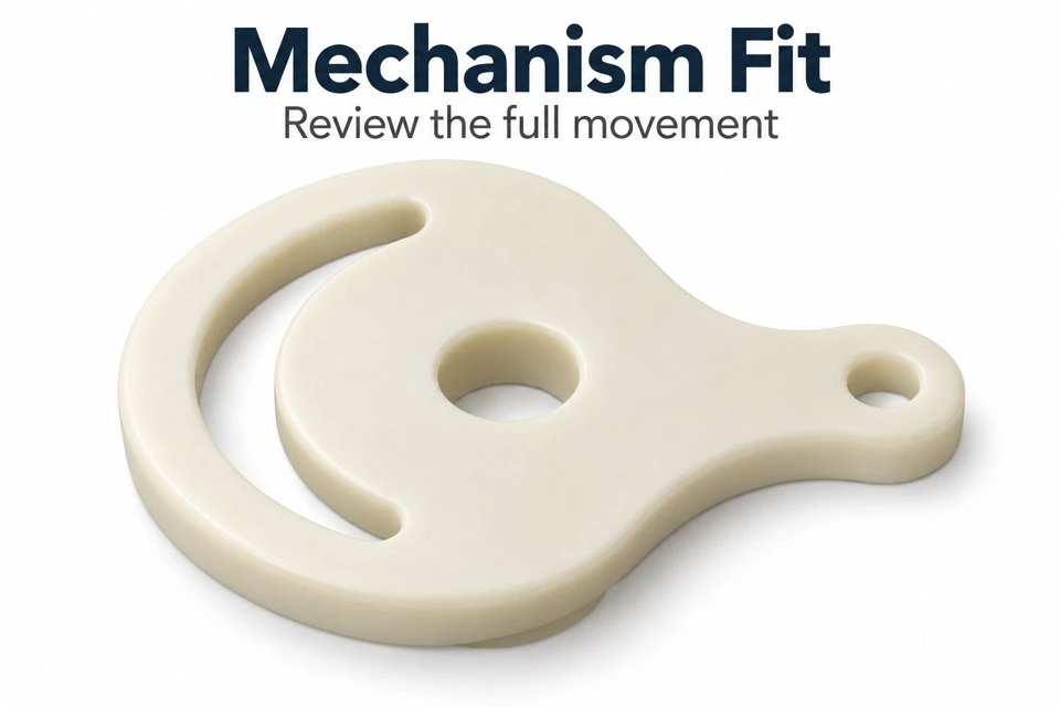
Check the complete moving envelope, including the follower head, fasteners and any lever attached to it. A slot may clear the pin while the pin head strikes the raised hub. Likewise, a projecting tab can clear the frame at one position and collide with it halfway through the stroke. Review intermediate positions, not only the endpoints. Small mechanisms often have their tightest clearance where the movement changes direction or passes a nearby support.
Also inspect the follower's engagement through the plate thickness. If the follower enters at an angle, contact may concentrate on one edge. The cam should not be expected to correct poor alignment elsewhere in the assembly. Locate the pivot and follower supports from agreed references, then assess their relative position. A transparent assembly model or a sectioned view can make the intended engagement much clearer for both the buyer and the molding review.
Which cam details affect mold construction?
An open through-slot may be formed in the main mold opening direction, depending on the overall shape. Side-facing pockets, retaining lips or enclosed cross holes can introduce additional tooling requirements. Discuss these features before the design is released. A small retention feature added late can change the tooling approach even when the main plate remains unchanged. Where possible, explain the feature's purpose so alternative arrangements can be considered without losing the intended function.
Draft on a slot wall changes its width over the thickness. Specify the level at which the functional width is controlled, and review the follower contact zone accordingly. The hub-to-plate transition and the narrow sections around the slot also deserve attention. Local thickness changes can influence cooling and the final shape. Gate position, flow around the slot and ejector contact should be evaluated together, with functional contact surfaces clearly identified on the drawing.
How should end stops and overloads be handled?
The end of a slot is not automatically a suitable machine stop. If the drive continues after the follower reaches the slot end, the resulting force can differ substantially from normal running contact. Specify whether another part stops the movement, whether the drive limits its force or whether the cam is intended to absorb that event. These are mechanism decisions that need to be stated explicitly rather than inferred from a rounded slot end.
Consider a jammed follower or an obstructed output as a separate operating condition. Explain what the equipment is expected to do when movement cannot continue. A controlled shutdown, a slipping drive and a replaceable sacrificial element represent different design intentions. The custom molding scope should follow the approved intention. No unsupported overload protection claim is made for the concept plate, and an ordinary visual check cannot establish its behavior during a jam.
What sample checks reveal functional problems?
Dimensional inspection should locate the slot path relative to the pivot reference, then check the width, hub geometry, plate thickness and any attachment holes. Checking the outside contour alone misses the geometry that creates the motion. A fixture or profile measurement can be useful for a curved path, provided the method is agreed. Mark critical areas where a small profile deviation changes the output movement more than it would elsewhere along the slot.
Install trial parts with representative shafts and followers and move through the full stroke in both directions. Observe running effort, free movement during reversal, axial rubbing and the final output position. If cycling is required, define the load, speed, lubrication and inspection intervals before the trial. Record the acceptance criteria as measurable outcomes. A hand-operated demonstration can reveal interference, but it does not by itself establish production life or performance under the actual load.
What should accompany a custom cam enquiry?
Send the three-dimensional part model, a dimensioned drawing and an assembly view showing the pivot and follower. Include the movement sequence and identify the surfaces that drive, guide or merely provide clearance. State the preferred acetal grade, color, trial quantity and anticipated repeat quantities. If the cam replaces an existing component, explain the observed issue: inaccurate positioning, rubbing, cracking or wear may point to different interfaces and require different evidence.
For a design still in development, distinguish fixed machine interfaces from features that can change during the moldability review. Keep a revision identifier on the cam drawing and the matching motion information so that sample approval refers to the same geometry. Tooling and production supply can then be quoted around a defined component. Contact amanda@tjswks.com with your drawings, material requirements, mechanism details and quantities to discuss a custom POM slotted cam plate.
Hot Tags: custom pom slotted cam plates, China, suppliers, manufacturers, factory, bulk, cheap, low price, quotation, pom absorber parts, pom divider parts, pom manufacturing, pom pcbs, pom polishing parts, pom quenching parts


