


Tianjin SWKS Technology & Development Co.,Ltd is one of the most reliable manufacturers and suppliers of custom pp float valve levers in China. If you're going to buy bulk cheap custom pp float valve levers, welcome to get quotation from our factory. Quality products and low price are available.
Custom PP Float Valve Levers
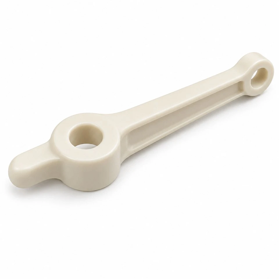
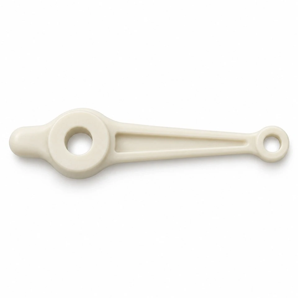
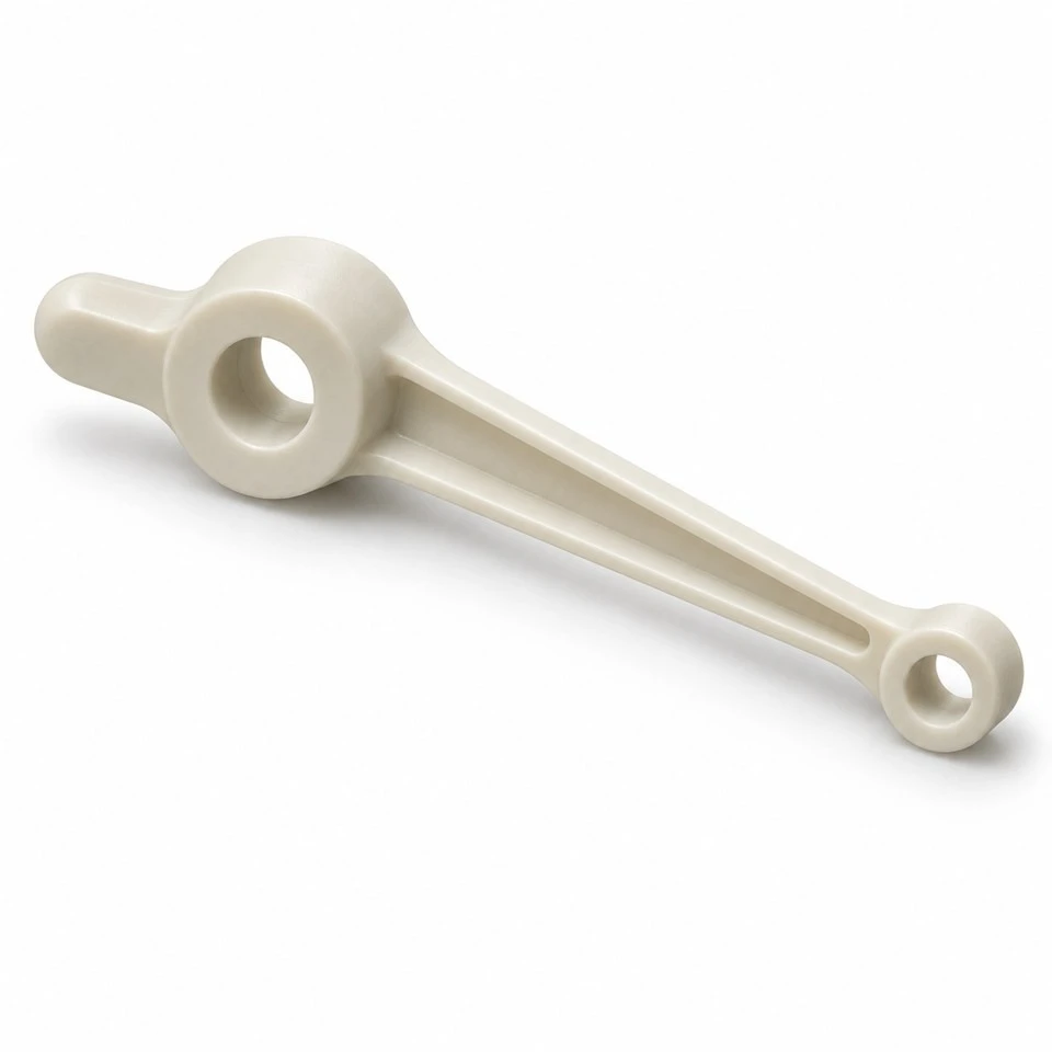
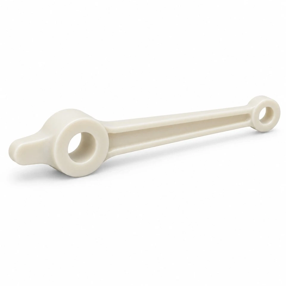
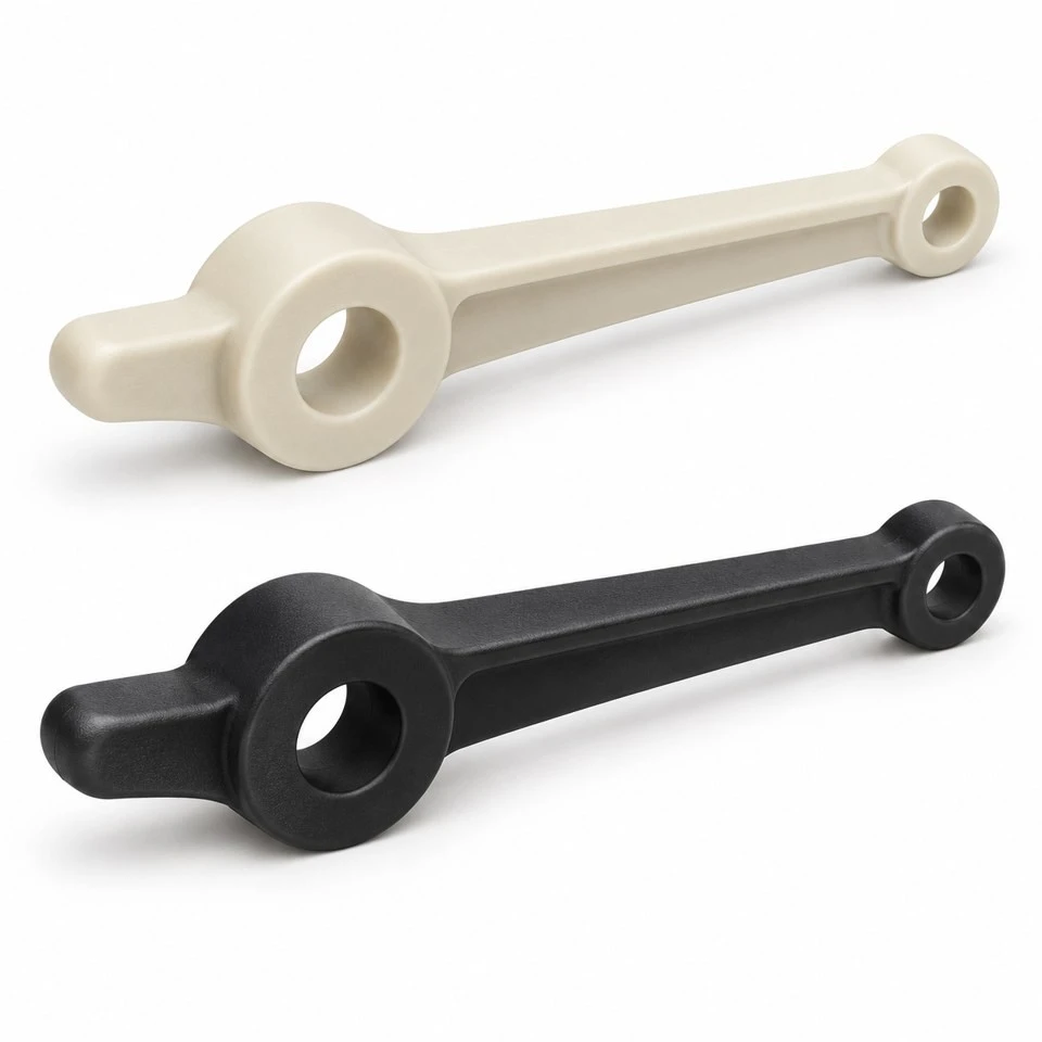
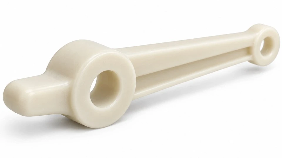
A float-controlled mechanism depends on the relationship between the float connection, pivot and valve contact point. SWKS develops custom injection molded polypropylene float valve levers around those three interfaces. The illustrated concept combines a reinforced long arm, a circular pivot boss, a linkage eye and a short rounded operating nose. Final dimensions and material grade follow the customer assembly. Send your drawings and quantity requirements to amanda@tjswks.com for quotation.
Material: ABS/POM/PA66/PP/PC/PA/PU/TPE/TPU etc.
Processing Service: Injection
Drawing: STP/STEP/IGS
Contact: amanda@tjswks.com / 0086-15222707659
How does the lever connect a float to a valve mechanism?
A float valve lever transfers movement from a float linkage to the valve operating point. Its pivot divides the arm into input and output regions, with their geometry establishing the relationship between float travel and contact movement. The illustrated concept has a long arm terminating in a linkage eye, a larger pivot boss and a short rounded contact nose. These features are developed around the complete valve arrangement rather than selected independently.
The molded lever is only one component of the mechanism. It does not include a float, valve body, sealing element or pivot pin. Its geometry alone cannot establish shutoff performance or a pressure rating. Provide the mating arrangement and operating sequence so the required motion can be understood. The illustrations represent a custom design concept and do not identify a tested replacement for any particular float valve model.
Which pivot references determine the operating geometry?
Specify the pivot axis and its location relative to the float connection and valve contact point. These distances determine how motion and force are transferred through the lever. Include the resting position and the required positions at the ends of travel. A drawing with only the overall arm length leaves important functional relationships undefined, especially where the short contact nose works against a separate plunger or pad.
Show the pivot support in the housing, including the width available around the boss. Identify the axial seating faces and any spacers that establish the installed position. The pivot should be referenced to the same assembly datums used for the valve and float connection. This helps the inspection plan focus on the geometry that controls the mechanism rather than relying on an approximate outline or a sample placed on a flat surface.
What should be specified for the float linkage eye?
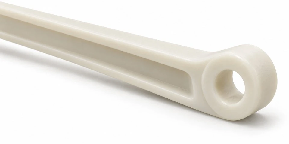
Provide the pin, hook, rod or other component that joins the float to the long arm. The round eye in the concept is a starting interface, with its diameter, thickness and edge shape defined from that mating part. State whether the connection rotates, slides or remains fixed during use. Different connection methods can require different clearances and retention arrangements even when the opening has the same nominal diameter.
Include the range of movement around the eye and any nearby float body or linkage features. The end of the arm needs enough clearance to move without catching on adjacent parts. If a removable clip or another retainer is used, show the space required for assembly and servicing. The supply scope should state whether the quote includes only the molded lever or also specific hardware. An unspecified float attachment is not automatically included.
How does the short nose contact the valve operating part?
Show the mating plunger or contact pad and describe the movement between it and the lever nose. The contact may shift as the lever rotates, so its surface should be reviewed over the useful travel range. A rounded tip can form part of that interface, but the final radius and contact width depend on the actual arrangement. Mark the regions where flash, a parting line or a raised gate mark would interfere.
State whether sliding or repeated rubbing occurs and identify the mating material and surface finish. An acceptable initial fit does not by itself establish wear behavior. If contact durability is important, define the force, travel, cycle and environment for a representative test. The lever should not be assigned a universal service life from its appearance. Any accepted surface treatment or finishing step needs to preserve the controlled contact geometry.
What force and travel information is needed for review?
Provide the force required at the valve operating point and the available force from the float linkage, together with their directions through the travel. Include the float configuration or the relevant force information supplied by the equipment designer. The lever relationship needs to be assessed at the operating angles rather than assumed constant from an overall length ratio. Position and contact direction can change together as the arm turns.
Identify any defined stop, stalled condition or installation load that the equipment specification requires the lever to tolerate. These conditions should have clear acceptance criteria. An arm that meets the intended operating movement may respond differently if it is used as a manual handle during assembly. Explain the expected handling procedure so the design review can separate normal duty from unintended forces and avoid leaving important requirements to an operator's judgment.
Where should rotation stop in the assembled valve?
Define the opening and closing travel limits and identify which assembly features provide the stops. The lever should not be assumed to stop at the correct point simply because the float reaches another component. Show the float, housing and valve operating element at both limits. This can reveal interference at the arm, pivot boss or linkage eye before a mold is built around an incomplete movement model.
If a molded stop feature is required on the lever, include its contact surface and the load it carries. The concept images do not include a separately qualified stop arrangement. A stop can change the force path through the arm and pivot, so it needs consideration with the complete mechanism. Functional samples should be checked through the intended travel in the representative housing, using the mating components and assembly sequence specified for production.
When can polypropylene be considered for a wet mechanism?
PP can be considered where the selected grade suits the mechanical duty and liquid exposure of the lever. Provide the fluid, temperature, concentration of relevant additives and cleaning conditions. A part that normally contacts water may also encounter another substance during maintenance or storage. Describe those conditions rather than relying on a broad statement of water compatibility. The complete resin formulation needs to be considered for the intended environment.
State the approved grade where one exists, including color and any required documentation. Natural and black illustrations show appearance options; they do not establish equivalent formulations or a material classification. Requirements for potable-water contact or another regulated use should be identified for the specific grade and supply scope. Do not infer compliance from the generic PP name or the appearance of a smooth molded component.
How can arm reinforcement fit within the available space?
The concept uses a low longitudinal rib beneath the long arm. Its height and thickness should be reviewed with the space available in the valve assembly. A deeper rib may change stiffness but also interfere with the float linkage or housing. Supply the surrounding envelope, including travel positions, so the reinforcement can be developed with the mechanism rather than added after the arm outline has already been fixed.
Review transitions around the pivot boss, rib roots and linkage eye. Abrupt thick intersections can affect cooling and the shape of nearby surfaces. The molding review should consider the force path as well as filling and ejection. Avoid treating added material as an automatic solution to every load requirement. The final geometry, material and agreed validation method should be assessed together against the defined operating and handling conditions.
What fit is needed at the pivot bore?
Provide the pivot pin diameter, material, finish and permitted variation. State whether the pin is fixed in the support while the lever turns around it, or whether another movement arrangement is used. Include lubrication and contamination conditions where they affect the interface. The required clearance depends on the actual function and environment; it should not be selected from the bore diameter alone without the mating information.
Also define axial clearance around the boss and the method used to retain the pivot assembly. A lever may rotate freely in an open sample fixture but bind when the housing is tightened. Show washers, shoulders and support faces that control the installed width. If a secondary bore operation or another manufacturing step is required to meet the drawing, agree it in the quotation rather than assume it is either included or unnecessary.
Which checks support approval of the first molded samples?
An inspection plan can cover pivot bore size and position, linkage eye location, contact nose profile, boss width and overall arm shape. Choose datums that reflect the installed references. Where a fixture is used, describe how it supports the part without forcing it into the desired shape. Record resin identity, drawing revision and inspection condition so the dimensional results remain associated with the component actually tested.
Functional approval should check assembly, free movement, useful travel and the agreed contact behavior with representative mating parts. Define any duty test and acceptance criteria before comparing samples. If a change to the float, plunger or housing is accepted during development, update the assembly information accordingly. A successful test with modified mating parts should not be treated as approval for a different production arrangement that was not evaluated.
What should be included in a custom quotation request?
Send an STP, STEP or IGS model and a dimensioned drawing where available. Include the float connection, pivot support, valve contact part, travel limits, force information and working environment. State the required PP grade and color, first order quantity and expected repeat demand. For a project starting from a sample or sketch, identify the features that must remain and the operating problem the new design is intended to resolve.
Use separate part numbers for similar levers with different pivot distances or contact profiles. Agree the hardware scope, inspection records and packaging requirements before production. Packaging should protect the arm from deformation and keep debris out of the bores and contact area. Repeat orders should reference the controlled drawing and the mating arrangement used for approval, with changes to the mechanism communicated before another batch is released.
Contact amanda@tjswks.com to discuss a custom PP float valve lever for your equipment.
Hot Tags: custom pp float valve levers, China, suppliers, manufacturers, factory, bulk, cheap, low price, quotation


