


Table of Contents
- What ENGEL introduced in 2026
- How the viper 6 fits into the connector cell
- What the connector output figure represents
- EVA and operator-confirmed machine changes
- What precision industrial parts buyers can verify
- Applying the lessons to an OEM quotation
ENGEL's 2026 announcements paired a new linear takeout robot with an integrated injection molding cell and described a separate development in machine-side process assistance. For buyers of small industrial parts, the news matters because it connects the press cycle with what happens after the mold opens, and with the decisions operators make when the process changes.
What ENGEL introduced in 2026
ENGEL placed two different kinds of automation in focus in its 2026 announcements. For Fakuma, it introduced the viper 6 linear robot as part of a connector molding cell built around the all-electric WINTEC e-win 1800. It also described a production assistant that can relay an approved change to the machine control system after the operator confirms. The first development focuses on equipment handling within a cell. The second concerns how a production team diagnoses a problem and authorizes a response.
The company's October 1 announcement for Fakuma identified the connector and the production equipment. Its October 28 Plastimagen announcement described the connector cell again as part of a wider group of exhibits that also included a precision molding application on the victory electric 220. These examples connect high-volume repeatability with practical control of handling and inspection. They give industrial buyers a way to discuss how a part will be produced once tooling is complete.
ENGEL's Plastimagen announcement also paired the tie-bar-less victory electric 220 with a medical plunger exhibit. That was a different demonstration with a different production goal. For a small technical part, an equipment comparison should start with the intended tool and the proposed method of removing the part. Ask what clearance the end-of-arm tooling needs, what inspection can happen without disturbing the cycle, and where the operator must access the tool during a changeover. Those questions can determine whether an attractive machine specification translates into a practical production cell.

Illustrative image of the process under discussion.
How the viper 6 fits into the connector cell
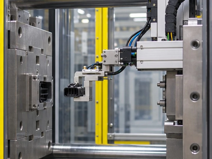
An injection molding cycle includes a period in which the tool opens and the parts are accessible. A takeout robot has to enter the available space, capture the parts or runner as specified by the tool design, and leave the mold area in time for the next cycle. The useful question for an OEM buyer is how the mold and handling system share that sequence. If a part has delicate locking fingers, contact faces or thin ribs, indicate where a gripper can touch it and where the receiving station must support it.
For some molded components, orientation matters after removal. A keyed connector body or sensor housing may be hard to feed into a gauge if it can rotate in a tray. A short trial should establish whether the part arrives in a repeatable position and identify the downstream step that sets the practical cycle. When several cavities deliver parts simultaneously, define whether parts are kept separate for traceability and how the inspection plan reacts to a difference between cavities.
Illustrative image of the process under discussion.
See our guide to optimizing injection molded parts for industrial automation equipment for a drawing-based approach to handling and fit.
What the connector output figure represents
ENGEL reported a connector component about 10 by 6 millimeters in size, made in a 128-cavity mold. At the quoted eight-second cycle, the arithmetic yields 57,600 pieces per hour before allowances for downtime or rejects. This figure belongs to the demonstration configuration. In a sourcing review, ask for the part-specific cycle assumptions, expected production yield and steps included in the quoted throughput. Tool layout, material, part handling, inspections and changeovers can produce a different result on another project.
The connector in ENGEL's exhibit was described as a component already produced in series. For a new OEM design, establish the cavity count after studying order volume, risk and the acceptance plan. Larger output per shot creates additional inspection questions. A buyer may need to know which parts belong to each cavity, what is checked at startup and how an individual cavity is identified in samples. A short listing of critical dimensions can make that conversation more concrete than a comparison of headline speeds.
EVA and operator-confirmed machine changes
In a separate September 9 Fakuma announcement, ENGEL described the ENGEL Virtual Assistant, or EVA, within its inject AI offering. According to the company, the assistant can interpret questions in the context of the machine and the production job, suggest a response, and send an approved change to the control system after the operator confirms. This is a separate example from the connector takeout equipment. It addresses the decisions made by people running and troubleshooting a cell.
For a factory comparing digital assistance, ask how a suggested change is reviewed against the part's approved process window. It helps to know what information is retained when a setting changes, how the affected tooling or production lot can be identified, and when subsequent samples need a physical check. On a dimensionally sensitive part, a machine trend and an inspection result answer different questions. A process record can show what occurred during molding, while a gauge or fixture confirms whether the part meets a drawing or fit requirement.

Illustrative image of the process under discussion.
What precision industrial parts buyers can verify
Use the component's actual installation to identify the features that must repeat. A small connector may require stable terminal openings and consistent latch geometry. A machine sensor bracket may depend on a defined mounting face and an adjustable slot. For a guide or locator, the important relationship may be the height and angle of the surface that first meets another part. Mark these features on the drawing and explain what happens if one drifts. This gives the mold review and downstream inspection a shared set of priorities.
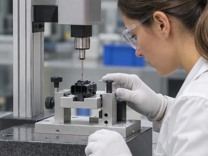
A handling plan can then be discussed with the part design. Where a gripper touches a cosmetic face or a narrow molded leg, determine whether a broader support or a different pickup position is needed. Identify when the customer requires cavity or production-lot traceability. Include the downstream check in a pilot run so the buyer can see how parts move from the press into the gauge, tray or next assembly step. A sample that fits by hand on a bench may still need adjustment before it can be fed consistently through automated equipment.
Illustrative image of the process under discussion.
| Area | What to verify | Evidence to request |
|---|---|---|
| Linear takeout | Repeatable part removal and positioning | Pickup surfaces, orientation at delivery, cavity identification |
| Molding cycle | Part-specific output assumptions | Cavity count, expected yield and inspection steps |
| Operator assistance | A controlled response to a process deviation | Change approval, lot records and sample checks |
| Dimensional inspection | Evidence that working features meet the drawing | Datums, inspection fixture and acceptance limits |
Related SWKS resources include design guidance for snap-fit and locking features and the custom plastic injection parts category.
Applying the lessons to an OEM quotation
Provide the 3D model, dimensioned drawing, approved material grade if known, and forecast quantity. A sketch of the mating assembly helps explain which tolerances matter. For high-volume orders, ask how cavitation, takeout, inspection and packaging contribute to the quoted cycle and cost. If clean handling or consistent orientation is required, describe how parts will be presented at the receiving station or in the shipment. The supplier can then define which steps belong in the machine cell and which are performed afterward.
Before tool approval, agree on samples and acceptance checks for features that are hard to inspect once the product is assembled. Discuss the treatment of startups, material changes and machine interventions, along with the sample evidence expected after each event. For replacement work, include the existing part and mark where earlier lots have shown fit or wear differences. Matching the review to the actual application helps the manufacturing team develop the tool around the performance requirements that the buyer intends to verify.
Discuss your precision molding project with SWKS
Send your STEP, STP or IGS file, technical drawing and required quantities to amanda@tjswks.com or call 0086-15222707659.
Reporting based on ENGEL's Fakuma 2026 announcements dated September 9 and October 1, and its Plastimagen 2026 announcement dated October 28.