


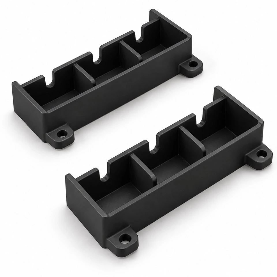
Tianjin SWKS Technology & Development Co.,Ltd is one of the most reliable manufacturers and suppliers of custom abs optical sensor light baffles in China. If you're going to buy bulk cheap custom abs optical sensor light baffles, welcome to get quotation from our factory. Quality products and low price are available.
Custom ABS Optical Sensor Light Baffles
An optical sensor can see more than the intended target when the space around it leaves unwanted paths for light. A custom molded baffle gives the equipment designer a physical way to define that surrounding space. SWKS supplies ABS optical sensor light baffle inserts developed from customer drawings, with channel walls, internal partitions and mounting features combined in one plastic component. Send the sensor arrangement, available envelope and expected quantities to amanda@tjswks.com to discuss a component that fits your instrument or electronic assembly.
Material: ABS/POM/PA66/PP/PC/PA/PU/TPE/TPU etc.
Processing Service: Injection
Drawing: STP/STEP/IGS
Contact: amanda@tjswks.com / 0086-15222707659
Where can unwanted light enter the sensor space?
Begin with the complete enclosure section. Mark the intended source, detector, target region and openings through which outside light can enter. The purpose of a baffle is difficult to define from a detector outline alone. A gap beside a cover, a reflective fastener or an opening for a cable may create a route that is absent from the isolated plastic model. Identify the paths that matter to the equipment before deciding how many internal walls the insert should have.
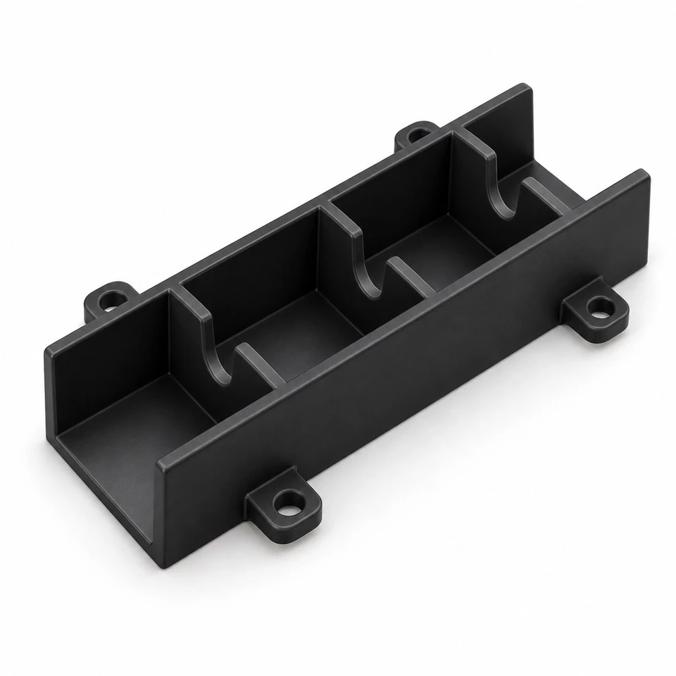
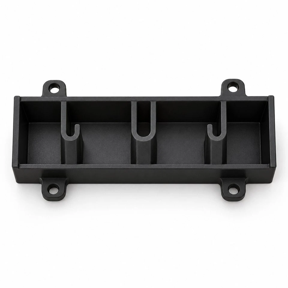
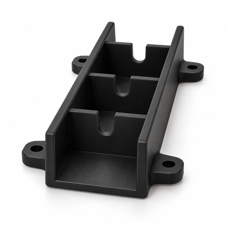
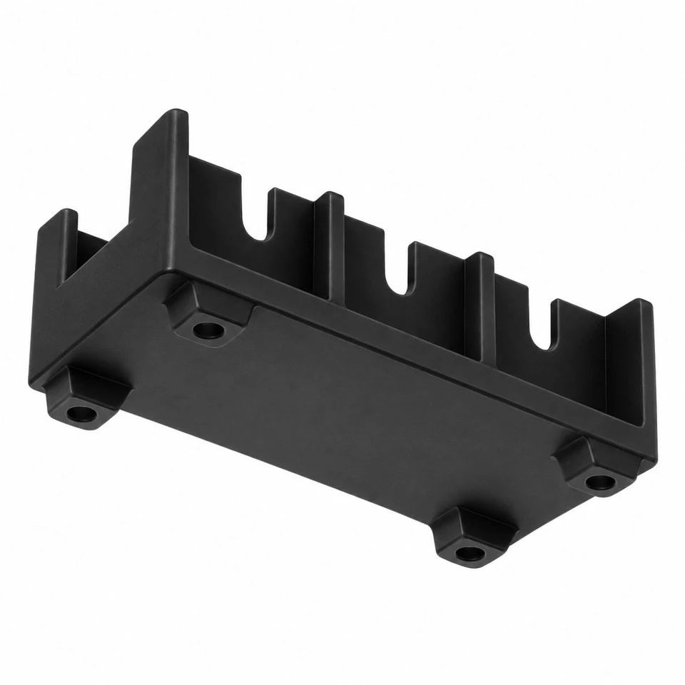
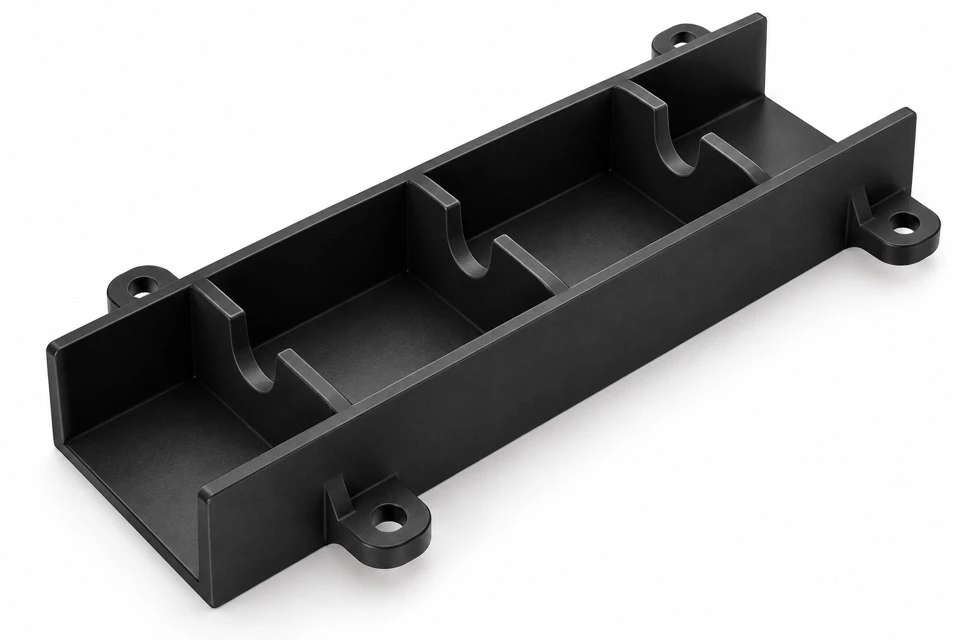
The concept shown here is an open channel with several notched partitions and external mounting ears. The plastic insert supplies mechanical geometry around an optical path. Its rendering does not assign an attenuation value, sensitivity improvement or operating wavelength. Those properties depend on the complete instrument and require suitable evaluation. Sensors, light sources, lenses, covers and electronic assemblies are separate from the molded component unless an agreed supply scope specifically includes them.
Which opening dimensions preserve the useful field of view?
A narrow opening may block an unwanted route while also obstructing the useful signal. Provide the working field of view and its position relative to the mounting references. Include the extremes permitted by the sensor, target and enclosure dimensions. The smallest clear space in a chain of partitions deserves particular attention. Several individually acceptable openings do not necessarily leave an acceptable passage when the parts are assembled at their tolerance limits.
Define the width and depth of each notch rather than assuming that identical-looking partitions must be identical. A source near one end of the channel may require a different local clearance from a detector at the other end. Keep-out regions should include lenses, connectors and any moving target. Where an optical analysis exists, translate its relevant envelope into clear mechanical references. That lets the mold review address a specified opening instead of relying on visual alignment in a rendering.
How should an open baffle meet the enclosure cover?
An open-top insert needs to be reviewed with the surfaces that close or surround it. Show the cover position, the clearance above the partition edges and any overlap along the side walls. A channel can look well shielded in an overhead image while leaving a gap above every internal wall. State whether that gap is acceptable or whether the mating cover needs a corresponding feature. The baffle and cover should implement one agreed arrangement.
Also consider the order of assembly. A cover rib that closely follows the insert may catch a cable or prevent the lid from seating if the insert is slightly displaced. Provide lead-ins and reasonable assembly access where required by the design. If the two parts touch, identify the intended contact region and the acceptable load. Unspecified interference between a cover and a thin partition can distort the component and change the opening that the sensor actually sees.
Does black ABS establish the required optical behavior?
Black appearance is a useful description of color, but it is not a measurement of the finished surface at the instrument's wavelength. Specify the wavelength range and any relevant reflectance requirement when these are controlled by the project. The material grade, color formulation and molded surface finish should be considered together. A component that appears dark to the eye still needs to be assessed under the illumination and observation conditions used by the equipment.
Discuss whether the project calls for a molded texture, a smooth tool finish or an approved secondary treatment. Texture belongs on the drawing or surface specification when it affects acceptance. It should not be added merely to conceal molding marks on a working optical surface. For any coating, agree the process, coverage, thickness allowance and durability requirements. The quotation should describe the actual proposed supply condition so that a sample is evaluated against the same surface that repeat production will use.
Which interfaces determine the insert's position?
Choose the locating features before applying tight dimensions to the channel. A component can have accurate internal openings and still sit in the wrong place if its attachment holes provide substantial movement. Show the seating face, locating edge or pin arrangement used by the enclosure. Distinguish the features that establish position from the fasteners that retain it. This makes the relationship between the optical passage and the instrument references easier to inspect and maintain.
Mounting ears need support appropriate to the attachment method. Tightening a screw against an unsupported tab can move the base or tip a thin wall. Include the fastener head, washer where used and tool approach in the assembly view. If snap retention is preferred, specify the mating thickness and removal method. The component should remain in the agreed position after assembly, maintenance and any operating conditions defined for the finished instrument.
What clearance is needed around boards and wiring?
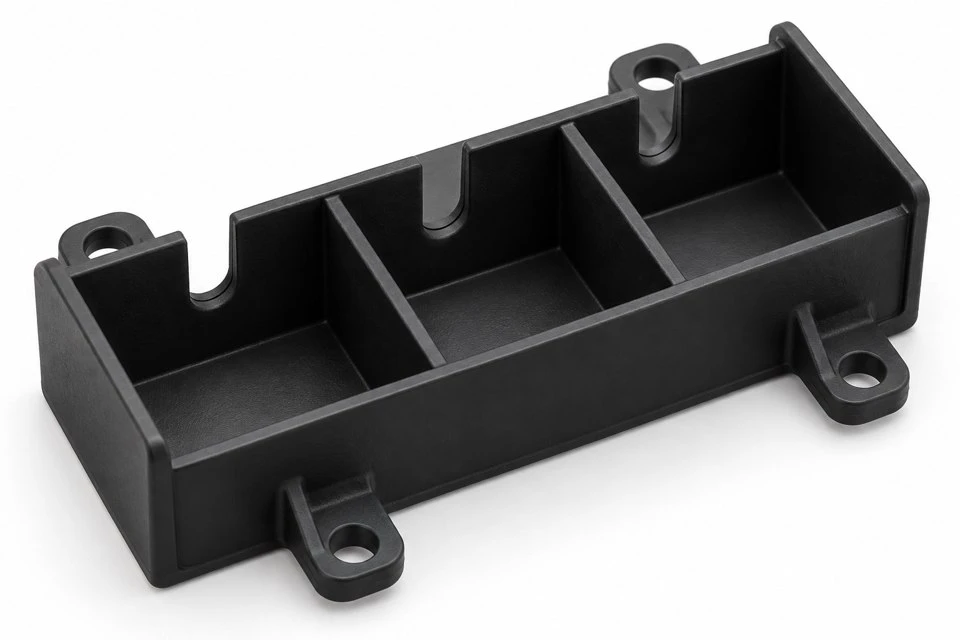
Include the populated circuit board rather than only its bare outline. Tall components, soldered leads and connector bodies can occupy space beside or beneath the insert. Cable routing deserves a separate review because a flexible wire can move into a path that was clear during initial assembly. Mark where a cable may pass and where it must be restrained. A baffle wall should not become an accidental cable clamp or load a connector when the enclosure is closed.
Check access for adjustment and service as well. The installer may need to reach a connector latch or alignment screw after the insert is in place. A mounting ear that is harmless during normal operation can obstruct that task. If the insert is removable, show the withdrawal route and the parts that must be removed first. These details help keep an optical packaging solution compatible with the actual maintenance sequence of the equipment.
How can the partition geometry suit injection molding?
An open channel with notches that open toward the mold release direction can provide a practical starting point for tooling discussion. Overhanging lips, enclosed side windows and transverse locking features need additional consideration. Explain the purpose of those features before the design is frozen. A small retention detail may influence the tooling arrangement more than a larger partition that releases with the main part. The mold proposal should be based on the complete component, including its mounting features.
Draft affects the clear opening through the wall height, so identify the functional measurement location. Thin free-standing partitions and abrupt wall intersections also need review during development. Mark the regions where flash, raised gate remnants or ejector marks would obstruct the passage or prevent seating. Cosmetic outside surfaces can have different acceptance criteria from an internal edge that defines the useful opening. Clear surface priorities help the supplier focus the tool design and inspection plan.
What temperature and electrical requirements should be declared?
State the temperatures expected near the insert, including heat from the light source, circuit board and enclosure environment. Local conditions can differ from the room temperature around the instrument. Provide any cleaning chemicals, handling exposure and storage conditions that matter to the material choice. When a particular ABS grade is mandatory, give its complete designation. The proposed resin should be approved for the project instead of being inferred from a generic material label.
Declare any flame classification, electrical insulation or electrostatic-control requirement separately. Standard black ABS should not be assigned these properties solely because it is used beside electronics. A specified grade and relevant documentation are needed where such requirements apply. Keep the supply scope clear: the molded insert is one component of the instrument, while electrical clearances and the qualification of the finished equipment remain part of the customer's assembly design and approval process.
How should the first molded samples be evaluated?
Inspect the locating features, passage geometry and the installed envelope against the approved drawing. Define how the component is supported during measurement, especially when the cover or mounting screws influence its final position. A free part measured on a bench may not represent the installed condition. If alignment between successive notches is important, specify the relationship directly and agree a suitable inspection method. A few separate width measurements may not describe the continuous clear path.
Then evaluate the insert in the representative instrument with the intended cover, source and detector. Include useful-signal checks and the unwanted illumination conditions that motivated the baffle. Record the material, surface finish and component revision with the test result. If the opening or surface needs to change, review the affected interfaces before releasing repeat quantities. The aim is a documented sample approval that connects the mechanical geometry to the instrument's agreed acceptance method.
What information supports an accurate custom quotation?
Provide a STP, STEP or IGS model plus a drawing marking the optical passage, mounting references and restricted surfaces. An enclosure section with the sensor and cover in position is especially useful. State the required ABS grade, color, surface finish, trial quantity and expected batch quantities. Identify any documentation or separate surface treatment required. Tooling and molded component prices can then be discussed against a defined scope rather than an unsupported assumption about optical performance.
For an existing instrument, describe the observed issue and the conditions under which it occurs. A photograph of the installed sensor area can help explain a cover gap or an obstructed adjustment point. Keep the model revision consistent with the enclosure used for sample approval. Contact amanda@tjswks.com with drawings, material requirements and quantities to discuss custom injection molded ABS optical sensor light baffles for your equipment.
Hot Tags: custom abs optical sensor light baffles, China, suppliers, manufacturers, factory, bulk, cheap, low price, quotation, abs glossy fittings, abs modular fittings, abs simple fittings, abs unpainted fittings, abs yellow components, CNC Machining ABS Plastic


