


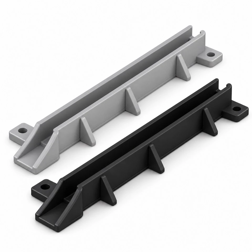
Tianjin SWKS Technology & Development Co.,Ltd is one of the most reliable manufacturers and suppliers of custom abs pcb card guide rails in China. If you're going to buy bulk cheap custom abs pcb card guide rails, welcome to get quotation from our factory. Quality products and low price are available.
Custom ABS PCB Card Guide Rails
A circuit board that slides into an equipment chassis needs a clear route from the service opening to its final connector position. A custom guide rail can support that route while fitting the enclosure's available space. SWKS offers injection molded ABS card guides designed around the customer's board outline and mounting arrangement. The molded channel, entry lead-in and attachment features form one component. Share your board and chassis layout with amanda@tjswks.com to discuss the interfaces before production tooling is defined.
Material: ABS/POM/PA66/PP/PC/PA/PU/TPE/TPU etc.
Processing Service: Injection
Drawing: STP/STEP/IGS
Contact: amanda@tjswks.com / 0086-15222707659
Where does a custom card guide fit in an enclosure?
The rail provides a channel along an available board edge. In many layouts, a second guide supports the opposite edge while the board travels toward a connector or another seating feature. The guide position establishes a physical route; the completed enclosure still determines retention, protection and access. A rail developed for one chassis should therefore be reviewed against that chassis rather than treated as a universally interchangeable electronic accessory.
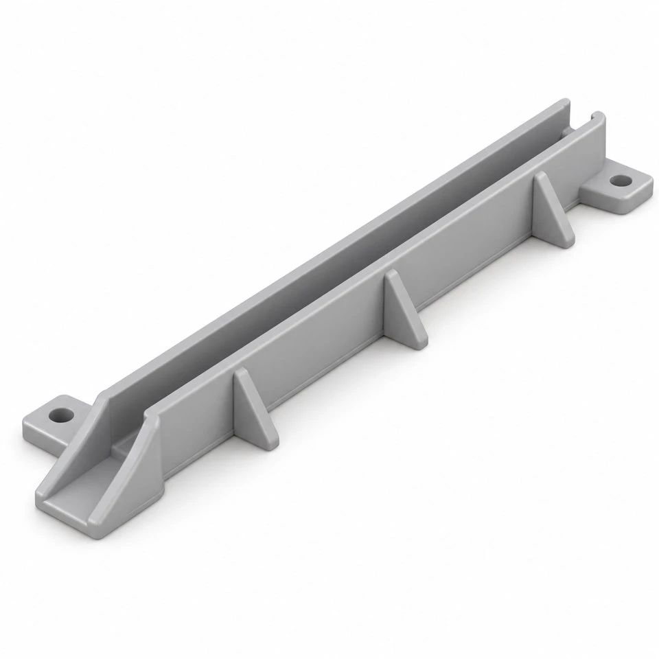
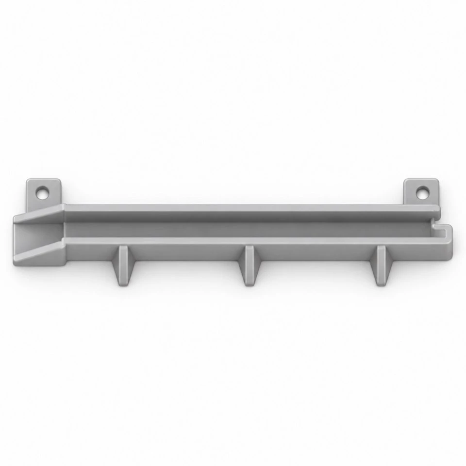
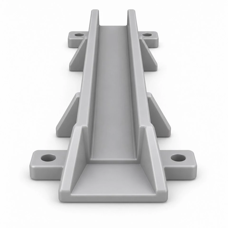
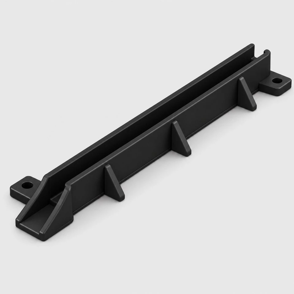
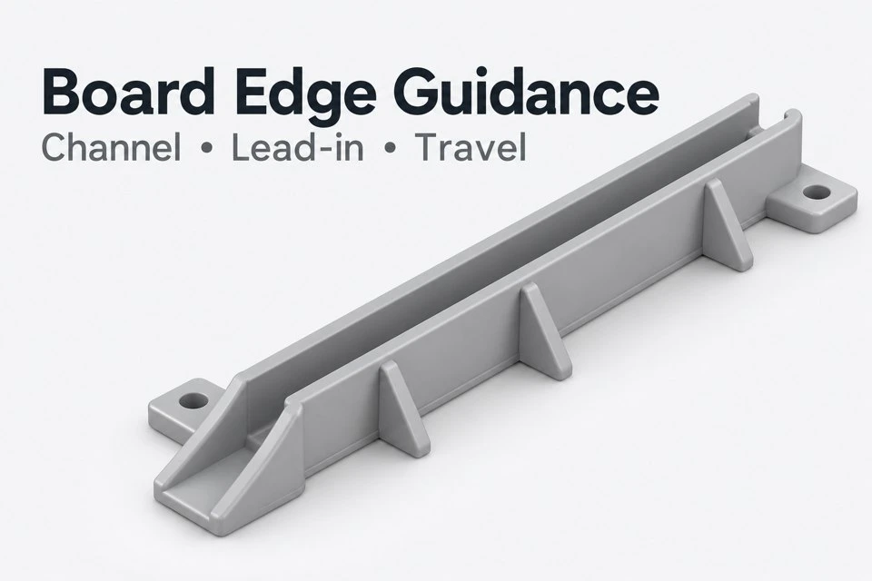
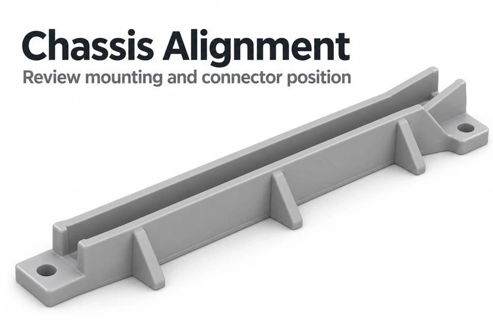
The concept images illustrate an open channel with external ribs and mounting ears. The supplied scope concerns the molded plastic component. Circuit boards, connectors, handles and chassis hardware are separate unless included in an agreed project. No operating temperature, electrical rating, flame classification or electrostatic-control property is assigned to the illustration. Those requirements need an approved resin specification and verification appropriate to the finished equipment.
Which board-edge details define the channel?
Begin with the finished board thickness, including its permitted variation. Then identify the edge region that may contact the guide. Copper features, protruding solder, components and assembly residues can occupy space close to that edge. A guide sized only from a nominal laminate thickness may encounter something that was omitted from the mechanical outline. Supply the board's mechanical restrictions and mark the contact area that the equipment designer permits.
Channel width and channel depth perform different jobs. Width controls the lateral fit around the edge, while depth establishes how far the board enters the rail. Excessive depth may bring the guide too close to nearby components; insufficient engagement may allow unwanted movement. Define both dimensions alongside the board-to-board or board-to-chassis clearance. The rail should be checked with the actual component population, not only an unpopulated rectangular board sample.
How can the entry help an operator start insertion?
A flared entrance can make the channel easier to find from the service opening. Its usefulness depends on the direction from which the operator approaches and the space available to see the board edge. A wider lead-in cannot correct every misalignment, and it should transition into the working channel without an abrupt obstruction. The entrance geometry should be evaluated with the board in the position an operator can realistically hold.
Consider what happens when one board edge enters before the other. Long boards can approach at an angle, especially when heavy components shift the balance. The two guide entrances should cooperate with that motion. Check whether the board can catch beneath an entry lip or strike a mounting ear. Trial assembly is valuable here because a smooth animation of perfectly aligned parts can hide the awkward movements that occur during real servicing.
Why must the connector position be reviewed separately?
The guide brings the board toward its destination, but the connector establishes its own mating requirements. Show the connector centerline, seating depth and permitted alignment in the assembly layout. Identify whether the board stops against the connector, a front panel or another positive feature. Using the end of a plastic channel as an accidental stop can prevent full mating or transmit insertion force through a surface that was intended only to guide.
Trace the positional relationship from the guide mounting reference to the connector. Board outline variation, chassis hole position and rail location all contribute. A rail that fits a loose board perfectly may still steer it slightly away from a fixed backplane connector. Where the equipment provides alignment features near the connector, include them in the model. The full mating arrangement should be assessed rather than asking the guide alone to absorb every dimensional variation.
What determines whether the rail should be ABS?
ABS is one material option for molded equipment structures, subject to the application requirements. Grade selection should consider the local environment, attachment loads and the documentation the customer needs. Provide the complete resin designation when a particular material is mandatory. Color alone does not identify a grade, and a visually similar rail made from another formulation may not satisfy the same purchasing specification.
Describe heat sources near the guide, the expected internal enclosure temperature and any cleaning exposure. Also state whether static-control or flammability requirements apply. Conventional ABS should not be assumed to provide an electrostatic-discharge function or a particular flame classification. If either property is required, the material and finished component need the appropriate review. The quotation can then identify the specified grade rather than making an unsupported claim based on the component's appearance.
How should the guides mount to the chassis?
Mounting ears can place fasteners outside the board channel, making the attachment easier to inspect. The chassis seating surface, fastener head and tool access still need to be shown. A screw tightened against an unsupported ear can distort the rail or change the channel alignment. Include washers, supports and any compression-limiting features in the assembly review. The intended tightening method is part of the attachment specification.
For a long guide, consider how it is located along its length. Multiple tightly constrained holes can impose stress if the chassis and rail do not align as expected. A locating arrangement that controls the necessary references while allowing an agreed amount of movement may be suitable, depending on the design. Snap attachment is another option when the mating panel thickness and installation direction are known. Retention and removal requirements must be defined for either approach.
What keeps the rail from interfering with nearby components?
Inspect the space around the channel, including the external ribs and mounting hardware. An external rib may be harmless beside a bare board edge but interfere with a tall component on a neighboring assembly. Board insertion also sweeps a volume through the enclosure. Check this swept space against cables, heat sinks and chassis features, especially when the board is tilted slightly at the beginning or end of its travel.
Service access deserves a separate check. A technician may need to grip the board, release a latch or disconnect a cable before withdrawal. A rail that supports easy insertion can still obstruct those actions. Include the front panel and handle in the layout if they control how the board moves. The guide should support the intended maintenance sequence rather than force the operator to bend the board around an avoidable obstruction.
Which channel features affect moldability?
The open-channel form can suit a straightforward mold concept when the surrounding features allow release in the chosen opening direction. Side hooks, enclosed cross holes and retaining undercuts may require additional consideration. Discuss the reason for each such feature early. A small clip added after the rail length is fixed can change the tooling approach more than a larger external rib that opens cleanly with the rest of the part.
Draft and wall thickness influence the working channel. A tapered wall means the clear width can vary with measurement height, so the drawing should specify the functional location. Thick rib intersections can also affect cooling and local shape. Gate and ejector locations should be reviewed to keep raised remnants away from the board-contact path. These details are easier to control when the critical channel surfaces are marked before the tool is designed.
How should straightness and sliding fit be inspected?
Define the rail's reference condition first. Measuring a long component unsupported on a table can give a different result from measuring it seated against its intended chassis supports. The inspection plan should state the relevant setup. Typical checks include the mounting pattern, channel width at an agreed level, usable channel length and the position of the guide surface relative to the attachment references. Cosmetic outside edges may be less important than those functional relationships.
A controlled board coupon can help compare sliding fit between samples, but it should represent the agreed board-edge specification. Record the coupon thickness, edge condition and test method. Functional trials should also use populated boards in the real chassis. Observe initial entry, travel, connector approach and withdrawal. If insertion force or repeated service cycles matter, define those acceptance criteria before testing rather than relying only on an operator's impression that the fit feels acceptable.
What should a buyer send for a custom guide project?
Provide the rail model or concept sketch together with the board outline and chassis mounting layout. Mark the board-contact zone, connector position and any keep-out areas. State the material grade requirement, preferred color, trial quantity and expected production quantities. Explain how the board is inserted and retained. If left and right guides differ, identify them separately so that drawings, samples and packaging remain unambiguous.
For an existing guide that needs improvement, describe the actual difficulty: catching at the entrance, loose sliding fit, connector misalignment or a broken attachment ear suggest different areas to investigate. Photographs of the installed guide and the board edge can make that discussion more useful. Keep the drawing revision consistent with the mating layout used for sample approval. Contact amanda@tjswks.com with drawings, material requirements and quantities to discuss custom ABS PCB card guide rails for your equipment.
Hot Tags: custom abs pcb card guide rails, China, suppliers, manufacturers, factory, bulk, cheap, low price, quotation, abs complex fittings, abs opaque fittings, abs purple components, abs smooth components, abs transparent components, abs transparent fittings


