


Gate location may occupy only a few millimeters on a molded component, but it can influence almost every important aspect of the injection molding process. It affects how the cavity fills, where weld lines appear, whether thick sections receive enough packing pressure, where a gate mark remains and how balanced the finished part is after cooling. For OEM engineers and buyers, understanding these relationships makes it much easier to review DFM proposals and compare mold quotations before tooling begins.
Why Does Gate Location Matter in Plastic Injection Molding?
A gate is the small opening through which molten plastic enters the mold cavity. Although it may look like a minor feature, its location strongly influences the entire filling and packing process. The gate determines where the flow starts, how far the melt must travel, where separate flow fronts meet and how effectively packing pressure reaches different areas of the part.
For simple molded parts, several gate positions may appear workable. For complex housings, brackets, covers or precision components, however, moving the gate by even a relatively small distance can change the location of weld lines, air traps, flow marks and deformation. This is why gate location should be reviewed during DFM rather than decided only after the mold has already been manufactured.
From a buyer perspective, gate location also affects visible gate vestige, trimming, automation, cycle consistency and sometimes unit cost. If a customer has cosmetic or assembly-critical surfaces, these requirements should be communicated before tooling begins.
How Does Gate Location Affect the Plastic Flow Path?
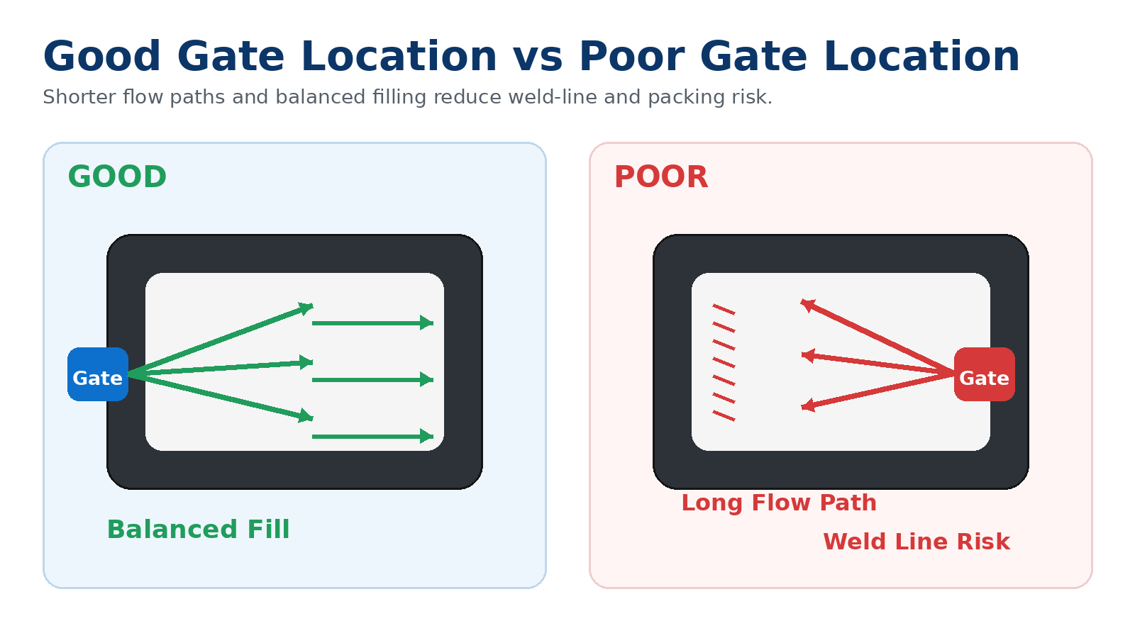
Molten plastic begins filling the cavity from the gate. In general, a shorter and more balanced flow path is easier to control than a very long or highly unbalanced path. When the melt must travel too far, its temperature and pressure gradually decrease. The final areas to fill may therefore be more vulnerable to short shots, weak packing, flow marks or dimensional variation.
For a long rectangular part, placing the gate at one extreme end may create a very long flow distance. Moving the gate closer to the center can reduce the maximum flow length, although the change may create two flow directions that later meet. The mold designer must therefore balance flow distance against weld-line position, appearance and functional requirements.
Large thin-wall parts are particularly sensitive to gate position because the melt cools quickly while traveling through narrow sections. A gate that works for a thick ABS housing may not provide the same filling performance for a thin-wall PP or PC part.
Why Can a Poor Gate Position Create Weld Lines?
Weld lines form when two or more flow fronts meet after traveling around holes, bosses, ribs or from separate gates. These lines can be mainly cosmetic, but in some applications they can also become weaker areas because the two melt fronts do not fuse as strongly as the surrounding material.
Gate position is one of the main tools used to control where weld lines appear. For example, if a molded housing contains a large opening, the melt may split around the opening and rejoin on the opposite side. By changing the gate position, engineers may be able to move the weld line away from a screw boss, snap-fit, sealing surface or highly visible cosmetic area.
Multiple gates can reduce flow length in large parts, but they also create additional points where flow fronts meet. More gates therefore do not automatically mean better quality. The best solution is the one that produces acceptable filling while keeping weld lines away from critical locations.
Where Should the Gate Mark Be Located on Cosmetic Parts?
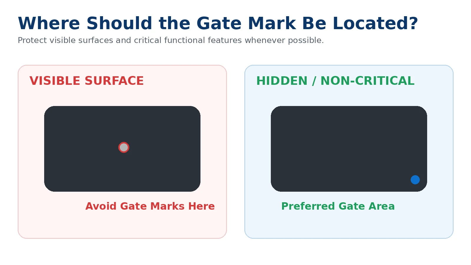
Every gate normally leaves some type of vestige after molding or degating. The size and appearance depend on gate type, material and trimming method. On an internal machine component, a small gate mark may not matter. On a visible enclosure, transparent cover or customer-facing housing, it can be an important cosmetic issue.
Whenever possible, visible A-surfaces should be identified before mold design so the manufacturer can place the gate on a hidden edge, back surface or non-critical area. Gate marks should also be kept away from sealing surfaces, sliding contact areas and precision assembly features when possible.
The requirement should be practical. Hiding a gate completely may require a more complex tunnel gate, hot runner or mold structure. Buyers should therefore communicate which surfaces truly matter rather than asking for zero visible marks everywhere.
How Does Gate Location Affect Packing and Sink Marks?
After the cavity appears full, the machine continues applying pressure for a short period. This holding or packing stage compensates for material shrinkage while the plastic cools. Packing pressure enters the cavity through the gate, so the gate must remain open long enough and be positioned so pressure can reach important thick sections.
If a heavy boss or thick region is very far from the gate, pressure may not compensate effectively before the gate freezes. This can increase the risk of sink marks, internal voids or dimensional variation. In some parts, placing the gate closer to the thicker region improves packing. In others, the better solution is to reduce excessive thickness through design changes.
This is why gate location should not be evaluated independently from wall thickness, ribs and bosses. Product design and mold design work together.
Can Gate Location Influence Warpage?
Yes. Gate position affects the direction of material flow, pressure distribution and molecular or fiber orientation inside the molded part. These factors influence shrinkage, and uneven shrinkage can contribute to warpage.
The effect is especially important for glass-fiber-reinforced materials such as PA66 GF grades. Fibers tend to orient with the material flow, so mechanical properties and shrinkage can differ between the flow direction and transverse direction. A gate position that creates strongly unbalanced orientation may make flatness more difficult to control.
Large flat housings can also deform when one region is packed more strongly than another. Balanced filling, appropriate gate location and effective cooling design should therefore be reviewed together when flatness is critical.
What Are the Most Common Gate Types?
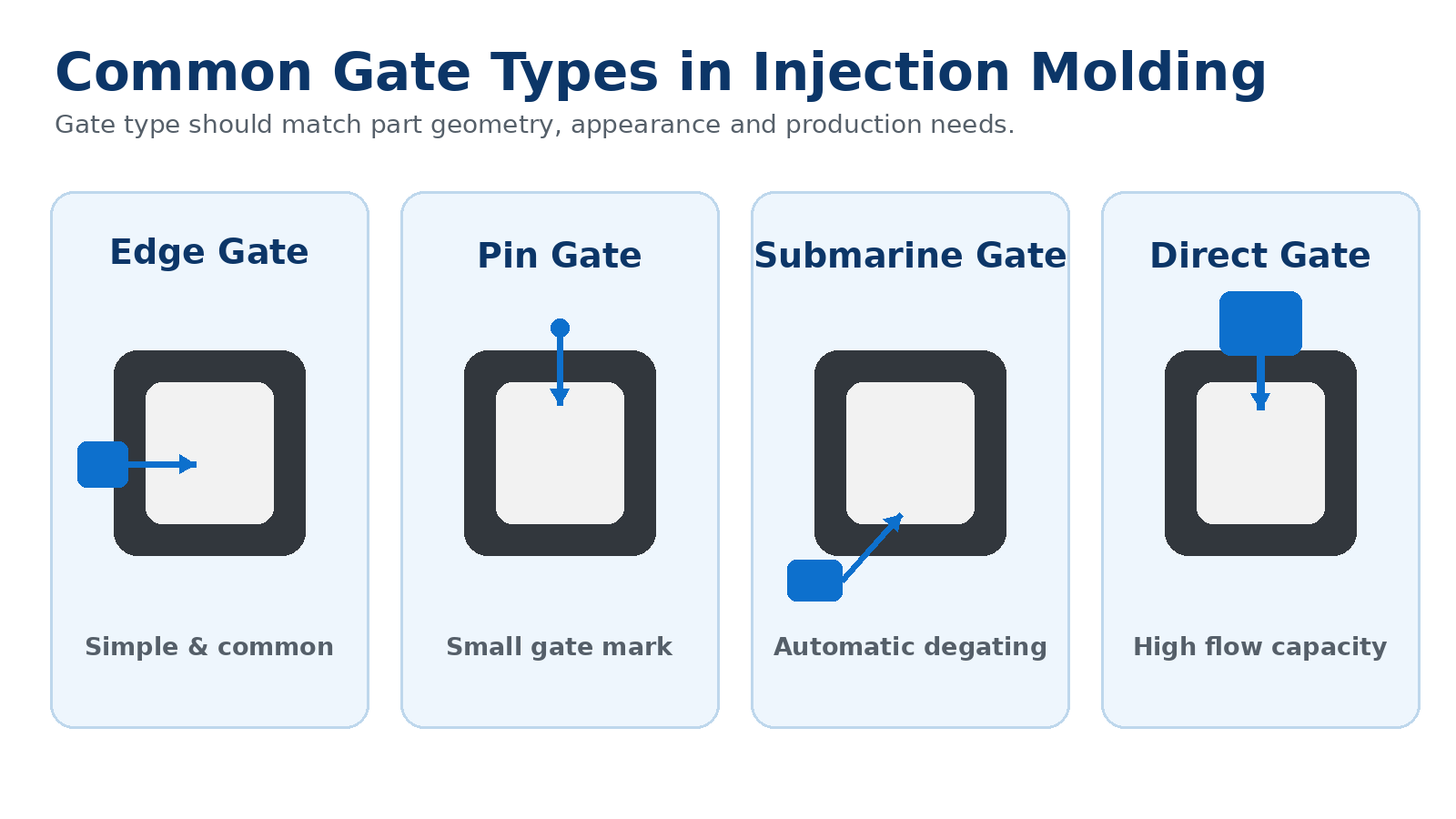
Edge gates are common and relatively simple. They feed the cavity from the parting line and are frequently used for general housings and industrial components. The gate vestige usually remains on the edge and may require trimming.
Pin or pinpoint gates can leave a relatively small gate mark and are often used when appearance or automatic separation is important. They may be associated with three-plate molds or certain hot-runner arrangements.
Submarine or tunnel gates enter below the parting surface and can often separate automatically during ejection. They are useful for automated production and for hiding the gate on a less visible area, but the geometry must be suitable and the small gate can create higher shear.
Direct or sprue gates provide a large flow area and can be useful for large parts or parts needing strong packing. However, they leave a larger gate vestige and may not be acceptable on cosmetic surfaces.
Fan, tab and other specialized gates can be used to distribute flow over a wider area, reduce jetting or improve filling of thin sections. Gate type should therefore be chosen together with gate position rather than treated as a separate decision.
How Does the Plastic Material Change Gate Design?
Different resins have different viscosity, shrinkage and sensitivity to shear. A gate arrangement that fills an ABS component reliably may not behave identically with PP, POM, PC or glass-filled PA66.
PP generally flows well but can exhibit relatively high shrinkage. Gate position and packing can therefore influence dimensional stability and warpage. POM is often used for precision mechanical parts, so gate vestige, packing and dimensional consistency may matter more than cosmetics alone.
PA66 and glass-filled nylon require attention to fiber orientation, moisture conditioning and structural performance. PC can require careful processing because of its viscosity and appearance requirements, particularly on transparent or glossy parts.
For critical projects, the exact production material grade should be confirmed before the mold design is finalized. Changing from an unfilled resin to a reinforced grade after tooling can change both flow behavior and shrinkage.
Should Large Parts Use Multiple Gates?
Multiple gates can be useful when a part is too large or thin to fill reliably from one location. They shorten individual flow paths and may improve pressure distribution. However, each additional gate creates another flow front and another possible weld-line location.
For cosmetic parts, the designer also needs to consider the number and position of gate marks. For structural parts, the strength of the weld-line regions may become more important. Sequential valve-gate hot-runner systems can sometimes control the filling sequence on large components, but they add tooling complexity and cost.
The decision should therefore consider annual production volume, part size, appearance requirements and quality risk rather than assuming more gates are automatically better.
How Should Gate Location Be Evaluated During DFM?
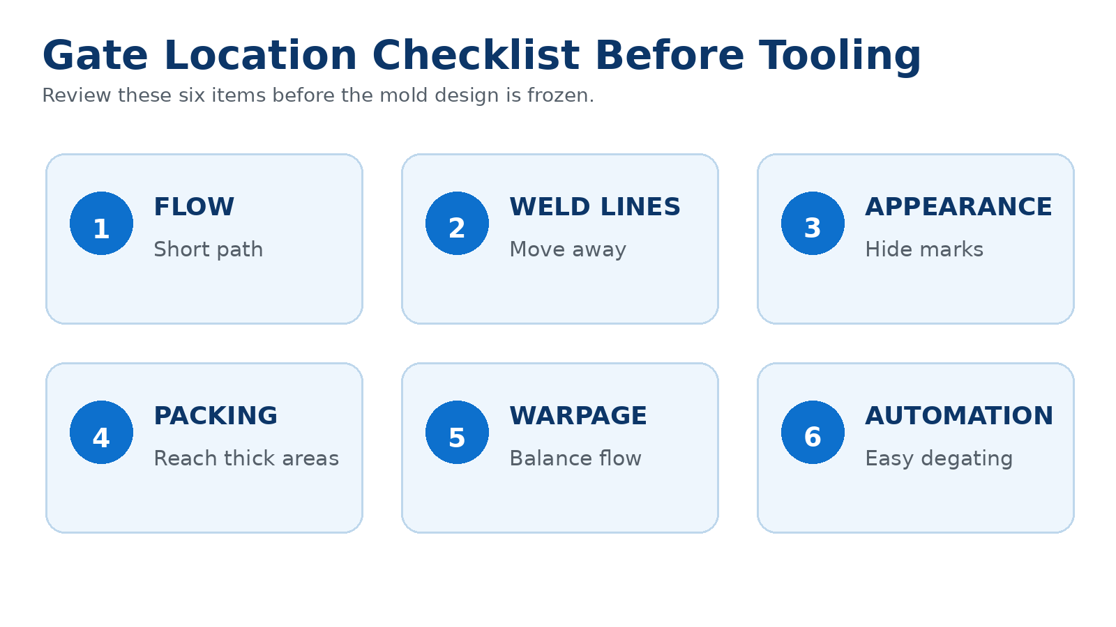
During DFM, the mold manufacturer should review the proposed gate together with part geometry, wall thickness, ribs, bosses, holes, cosmetic surfaces and critical dimensions. For complex components, mold-flow simulation may be used to compare different filling strategies before steel is cut.
A useful DFM discussion should answer practical questions: Where will the gate mark remain? Where will the flow fronts meet? Can pressure reach the thick sections? Is the flow path too long? Could the gate create jetting or excessive shear? Will the part eject automatically after degating? Does the proposed location interfere with assembly?
Customers do not necessarily need to choose the exact gate position themselves. However, they should clearly identify functional and cosmetic restrictions so the mold engineer can optimize the gate around real product requirements.
What Information Should the Buyer Provide Before Tooling?
Provide both a 3D model and a 2D drawing whenever possible. The 3D model allows the mold engineer to evaluate the complete geometry, while the 2D drawing identifies tolerances, cosmetic surfaces and critical dimensions.
Also state the production material, initial quantity and estimated annual volume. High-volume projects may justify a hot runner, multi-cavity mold or more automated degating method that would not be economical for a small production program.
If a surface cannot contain a gate mark, label it clearly. If a region is used for sealing, sliding, bonding or precision assembly, identify that as well. These details are often more useful than simply writing "no gate mark" on the entire component.
How Can You Compare Gate Proposals From Different Suppliers?
If suppliers recommend different gate positions, do not compare the proposals only by mold price. Ask each supplier to explain the expected flow path, gate vestige, weld-line location, trimming method and any risk to appearance or dimensions.
A slightly more complex gate solution may be justified if it significantly improves visible quality or production stability. On the other hand, an expensive hot-runner solution may not make sense for a low-volume industrial part with no cosmetic requirements.
The best gate strategy is the one that matches the actual application, production quantity and quality requirements.
Frequently Asked Questions About Injection Molding Gate Location
Can the gate position be changed after the mold is finished? Sometimes, but it may require significant mold modification. It is much better to review gate position before tooling is manufactured.
Is a smaller gate always better? No. A small gate can leave a smaller vestige, but it may restrict flow, increase shear or freeze too early for effective packing.
Can the gate be placed on a cosmetic surface? Technically yes, but it should be avoided when appearance matters unless the gate mark is acceptable or later finishing will hide it.
Does every injection molded part need only one gate? No. Large, thin or complex parts may require multiple gates or a hot-runner strategy.
Should the customer specify the gate position on the drawing? The customer should specify restricted and critical areas. The final gate position is normally best determined with the mold engineer during DFM.
Need Help Reviewing Gate Location for a Custom Plastic Part?
Gate location is a small feature with a large influence on injection molding quality. It affects filling, weld lines, gate marks, packing, dimensional stability, warpage and production automation.
For a new custom plastic component, the best time to review gate location is before mold manufacturing begins. SWKS supports custom plastic injection molding projects from drawing review and DFM through tooling, sample validation and mass production.
Send us your 3D model, 2D drawing, material requirement, quantity and application information. Our team can review the project and evaluate an appropriate molding and tooling strategy before production.