


Contents
- What are the main parts of an injection molding system?
- What does the hopper do?
- How do the barrel, screw and heaters work together?
- What is the nozzle and how is it different from a gate?
- What does the clamping unit do?
- What does the injection mold contribute?
- Why are cooling and temperature control part of the system?
- How is the molded part removed?
- What do the controls and drives contribute?
- Which supporting devices may be needed?
- How do these parts work through one molding cycle?
- Which marks can appear on the finished plastic part?
- How should buyers use this knowledge when reviewing a quotation?
- What information is needed before tooling approval?
In plastic manufacturing, the question "What are the parts of an injection?" usually refers to the equipment and tooling used for an injection molding operation. The main machine assemblies are the injection unit and the clamping unit. They work with a product-specific mold, a control system and supporting equipment to turn plastic raw material into a repeatable molded component.
Each assembly has a different job. Material must be supplied, prepared, delivered into the mold, cooled and released. Understanding those jobs helps an OEM buyer discuss a project more clearly: the molding machine provides the process, the mold creates the geometry, and the finished plastic part must meet the drawing and application requirements. This guide follows a conventional thermoplastic molding system; specialist processes can use different arrangements.
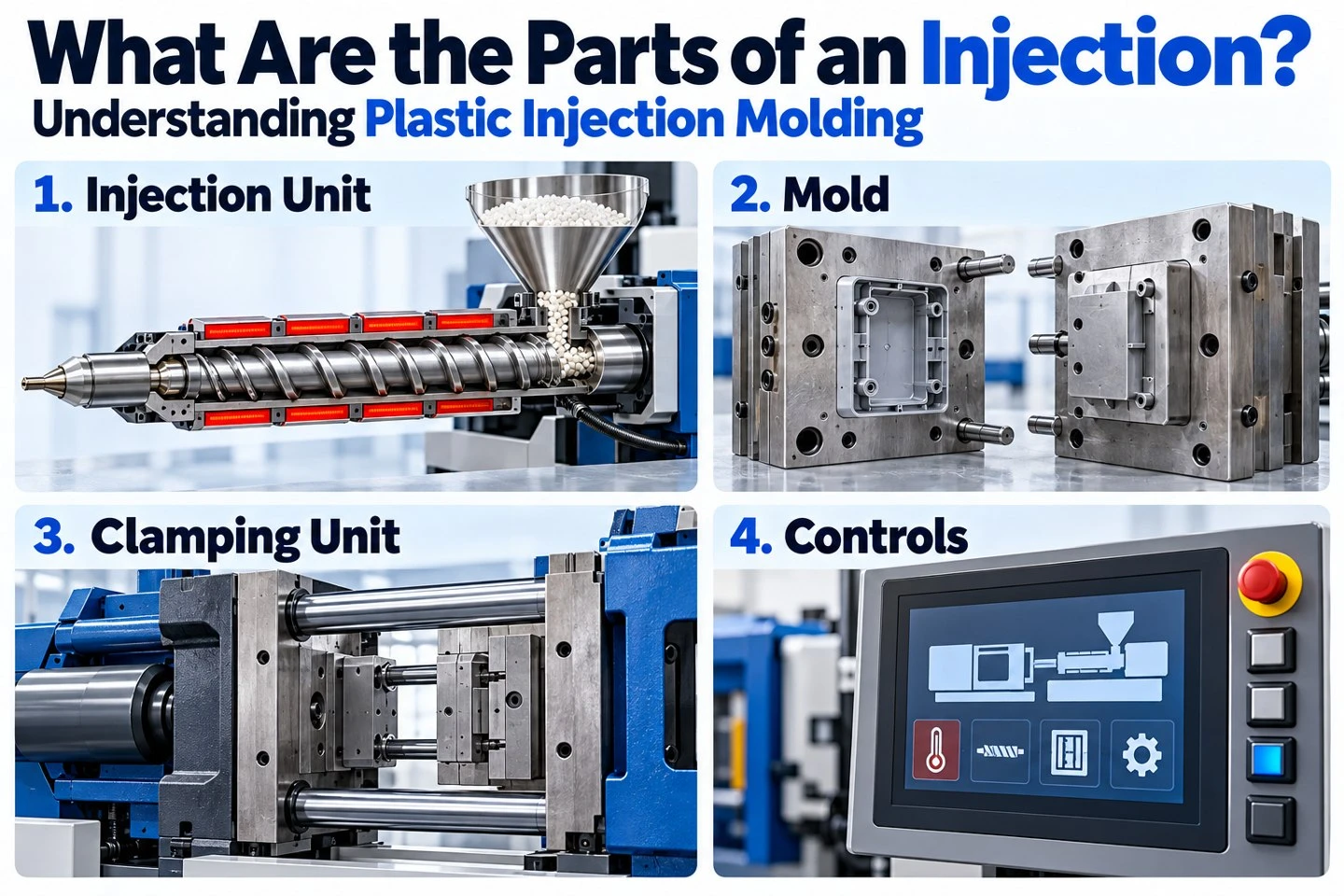
Overview of a conventional thermoplastic injection molding system. Concept illustration.
What are the main parts of an injection molding system?
It is useful to separate the system into three levels. At machine level, the injection unit prepares and injects material while the clamping unit opens, closes and holds the mold. At tool level, the mold contains the surfaces and mechanisms that form and release the component. At production-cell level, material handling, temperature control and part handling support a consistent operation.
These are related groups rather than a universal list of ten independent parts. For example, a screw and barrel belong to the injection unit, while ejector pins normally belong to the mold's ejection system. A dryer can be essential for a particular resin but is not necessarily built into the machine. Identifying the level avoids confusing a machine assembly with a tool feature or auxiliary device.
What does the hopper do?
The hopper receives plastic granules and supplies them to the machine's feed area. Depending on the production arrangement, material may be loaded manually or delivered by an automatic loading system. The hopper is therefore the beginning of the material route, but it does not by itself establish that the resin has been prepared correctly.
For a purchasing team, the important discussion is material identity and handling. Confirm the specified grade, color and any approved use of reprocessed material. Where drying is required, ask how preparation and exposure are controlled for that resin. A hopper filled with the correct-looking pellets does not provide evidence of the material grade or its preparation history.
How do the barrel, screw and heaters work together?
The barrel contains the plasticizing screw in a conventional reciprocating-screw machine. As the screw rotates, it conveys and works the material along the barrel. Heat from the barrel heaters and mechanical working of the material contribute to preparing the melt. The screw then advances during injection to deliver material toward the mold. Temperature and screw operation must suit the resin and the component.
These parts function as an assembly. The barrel provides the working chamber, the screw moves and prepares material, and the heaters support temperature control. Their existence does not establish a universal processing recipe. A reinforced nylon bracket and an unfilled polypropylene cover can require different material preparation and processing decisions, even when both are made by injection molding.
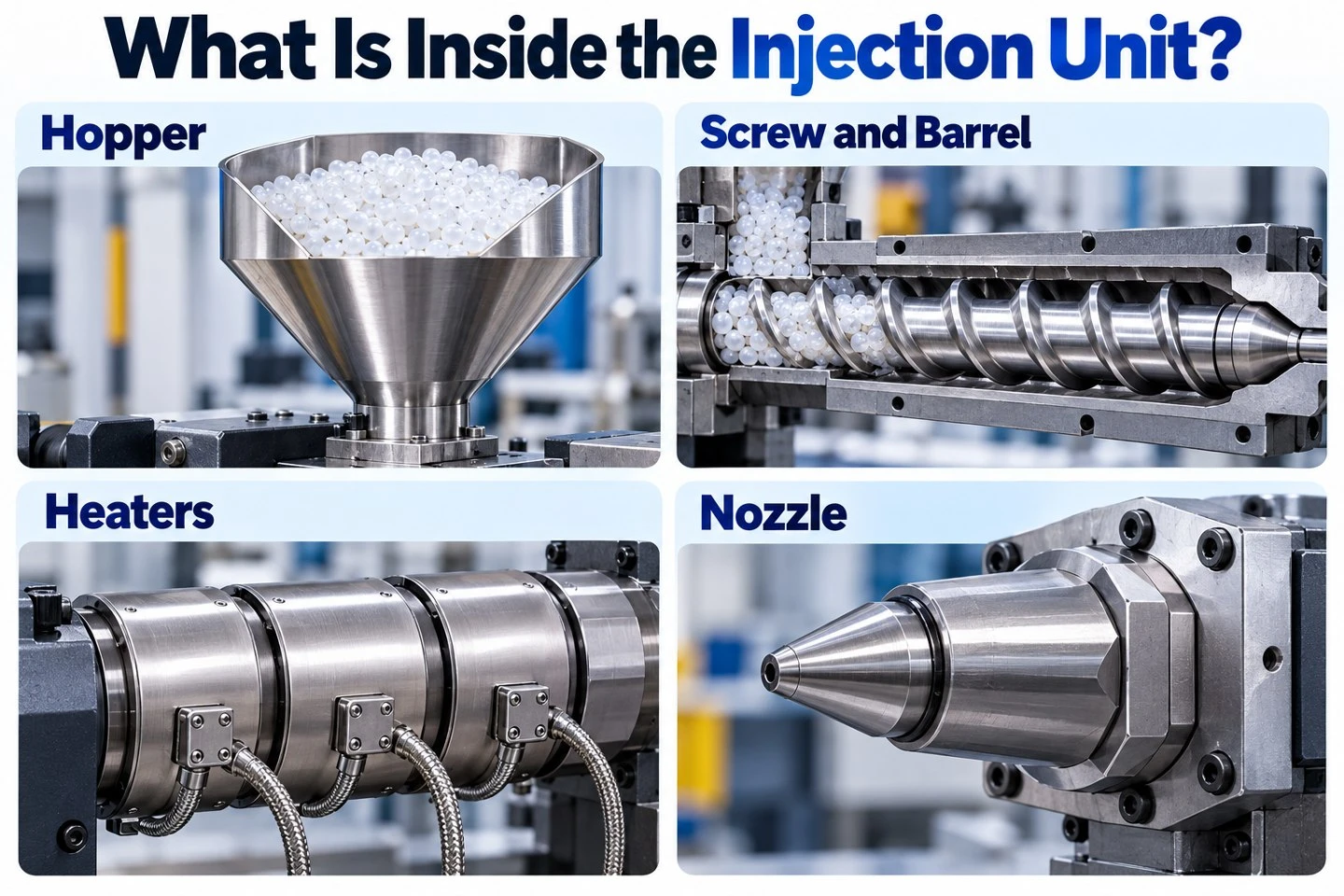
The injection unit prepares and delivers material; equipment construction varies.
What is the nozzle and how is it different from a gate?
The nozzle is the delivery connection at the front of the injection unit. It interfaces with the mold's inlet arrangement. A gate is the opening through which material enters the component cavity. In a conventional cold-runner tool, the material route can include a sprue and runner between the machine nozzle and the gate. Hot-runner designs use a different delivery arrangement.
This distinction helps during sample review. A visible mark on the finished component is often associated with the gate location or its removal, rather than the machine nozzle directly touching the product. If a face must remain cosmetic or contact another component, identify it before tooling. The manufacturer can then consider the feed arrangement together with filling and finishing requirements.
What does the clamping unit do?
The clamping unit supports the mold and provides the movement and force needed to keep it closed during molding. Platens carry the mold halves, and the moving arrangement allows the tool to open for part removal. Many machines use tie bars and a toggle or hydraulic arrangement, while other machine architectures differ. The exact construction depends on the equipment.
Machine selection involves more than stating a large clamping-force number. The tool must fit the available installation space, and the opening and ejection arrangement must suit the component. The injection unit must also be appropriate for the material quantity and process. For a custom order, the manufacturer should evaluate these requirements against the proposed mold and part rather than select equipment by overall product length alone.
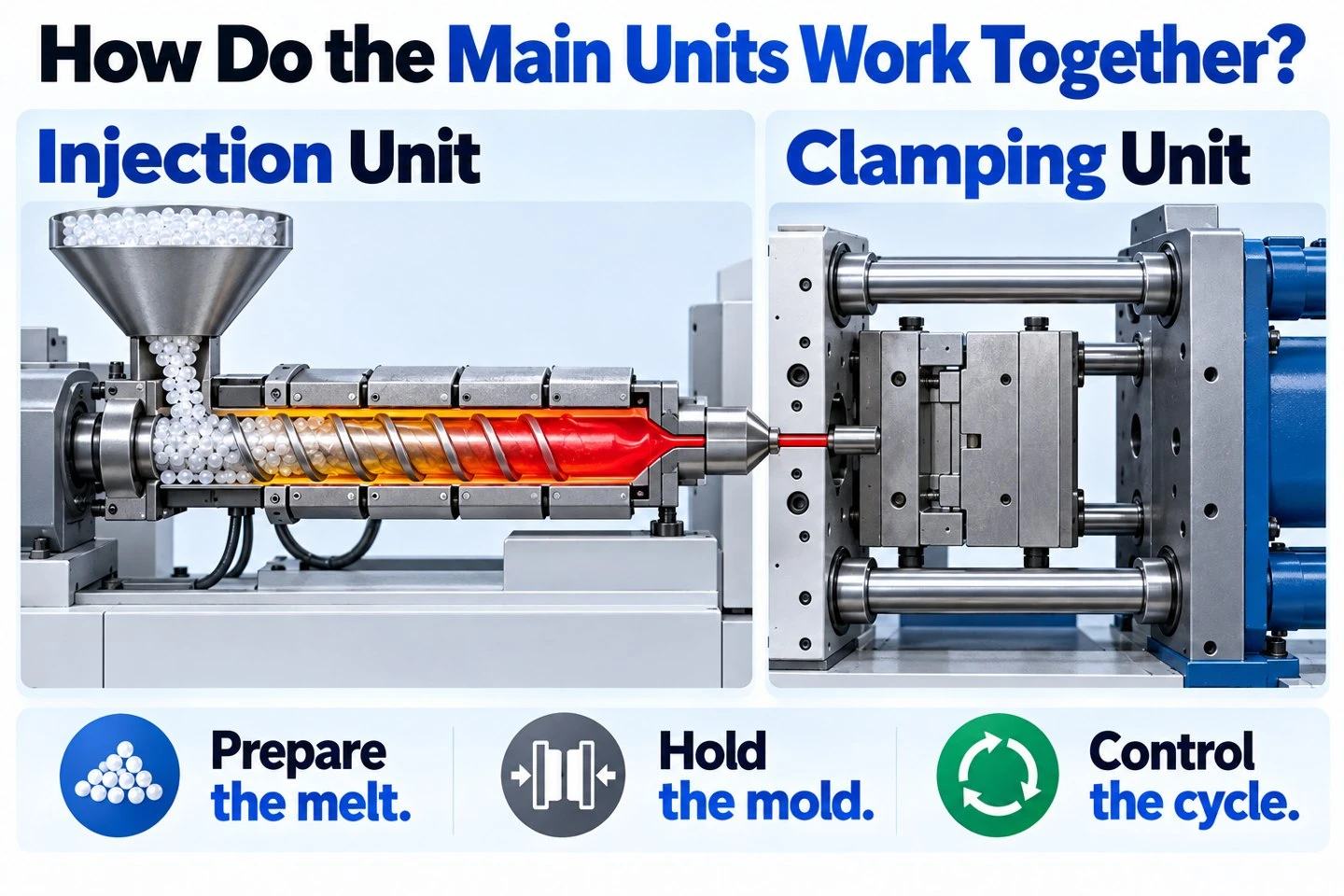
Material delivery and mold holding are coordinated with the machine controls.
What does the injection mold contribute?
The mold creates the component's geometry. Core and cavity surfaces define the space that the plastic occupies, while the surrounding tool structure supports alignment, material delivery, temperature management and release. A simple tool may open in one main direction. More complex geometry can require slides, lifters or other mechanisms, depending on the feature.
The mold is specific to the approved design. A change to a pocket, wall, mounting location or cosmetic surface can therefore affect tooling. Before the mold is manufactured, establish which model revision controls production and which drawing dimensions are critical. Our guide to draft angles in injection molded plastic parts explains one geometry issue that should be resolved at this stage.
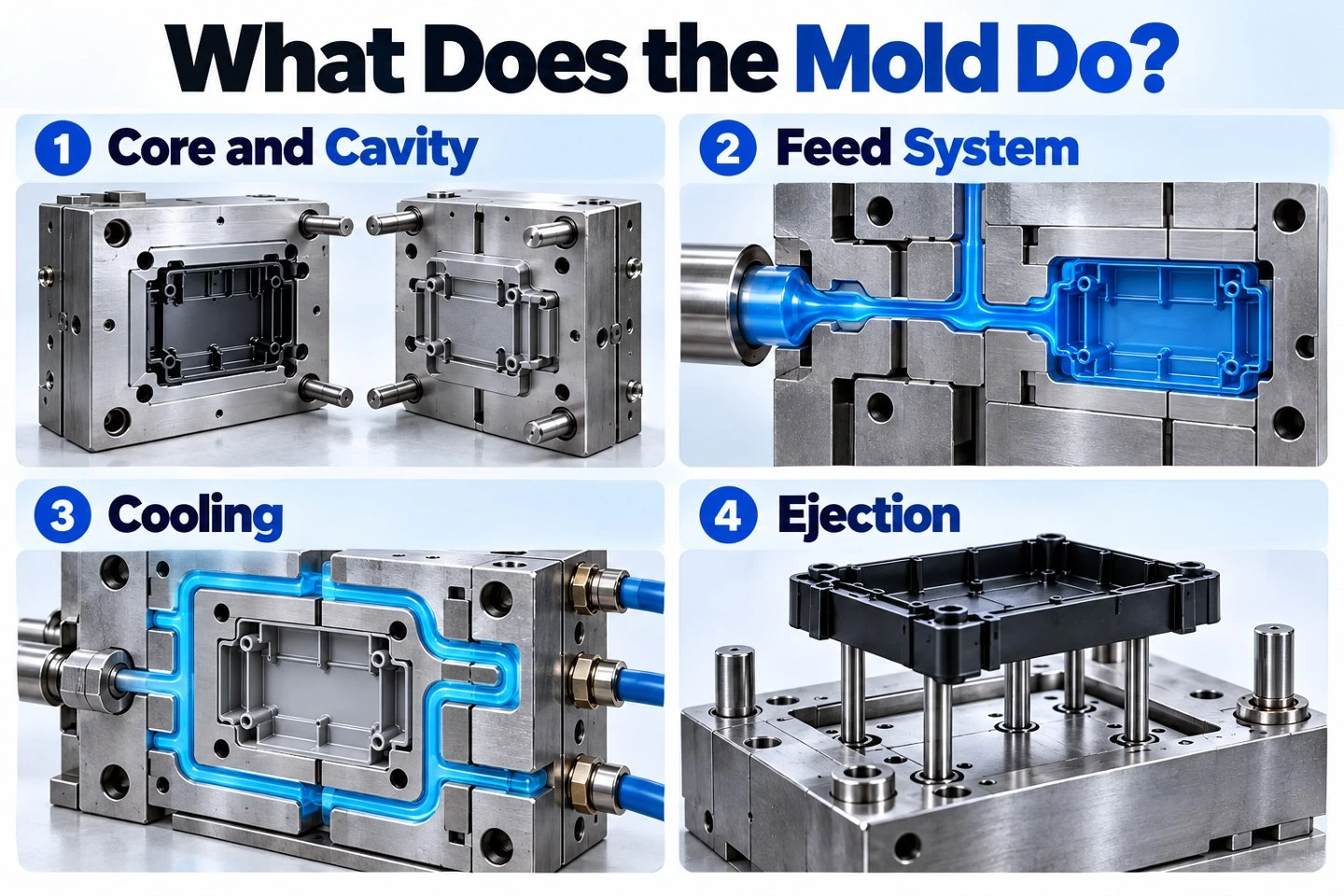
The mold forms, cools and releases the component. Functional concepts, not a tool drawing.
Why are cooling and temperature control part of the system?
The molded component must lose enough heat to retain its intended shape during release and handling. Mold temperature management helps establish the conditions under which that happens. Depending on the tool, this can involve internal channels, temperature-control equipment and other heat-transfer arrangements. The correct approach follows the resin, geometry and production requirements.
Cooling should be discussed in relation to the whole component. A thick mounting area and a broad thin wall do not present the same local geometry. An apparent cycle-time improvement is not useful if the released part fails the assembly or dimensional checks. For a fuller discussion of shape changes, see our article on warpage and dimensional stability.
How is the molded part removed?
After the mold opens, an ejection system helps separate the part from the forming surfaces. Pins are a familiar example, but sleeves, plates or other arrangements may be selected for different components. Part geometry, material and the permitted contact areas influence the design. A robot or operator may then remove the released component from the molding area.
Buyers should identify sensitive areas early. An ejection contact mark that is acceptable on a hidden underside may be unsuitable on a sealing surface or visible face. Review the expected contact areas against the drawing, and examine molded samples for both appearance and function. Being able to remove a component is necessary; releasing it consistently without unacceptable damage is the production objective.
What do the controls and drives contribute?
The control system coordinates the machine sequence and processing conditions. It manages the commanded movements and relevant temperature, pressure, position or timing settings, with available monitoring depending on the machine. Hydraulic, electric and hybrid machines use different drive arrangements to produce the required motion.
For an OEM project, repeatability matters more than a generic claim that one drive type is always better. Ask how the approved process is recorded and how changes are controlled. A machine name or touchscreen photograph does not replace sample inspection, material identification and production records. Equipment capability should support the requirements agreed for the actual plastic component.
Which supporting devices may be needed?
A production cell can include material loaders, dryers, color-dosing equipment, temperature controllers, chillers, robots, conveyors and inspection aids. Not every project uses every device. Their role is to support the material and handling needs of the operation, not simply to make the equipment list longer.
Consider a resin with specific drying requirements, a cosmetic housing that needs protected handling, or a small part that must remain separated by cavity during inspection. Each creates a different supporting need. The buyer should explain the material and finished-part requirements so the manufacturing team can plan the relevant controls. Requesting a generic accessory without explaining the problem may not produce the desired result.
How do these parts work through one molding cycle?
A simplified cycle begins with mold closing and clamping. The injection unit delivers the prepared melt into the tool, followed by a holding phase appropriate to the process. Cooling allows the component to become suitable for removal. The mold then opens and the ejection arrangement releases the part. Preparation of material for the next shot can overlap other stages, depending on the machine and process.
The sequence connects the assemblies described above. The injection unit cannot compensate for every unsuitable cavity feature, and the clamp alone cannot establish correct filling. Material, tool and machine must work together. Our article on incomplete filling and short shots gives an example of why a finished-part problem may require checks across several parts of the system.
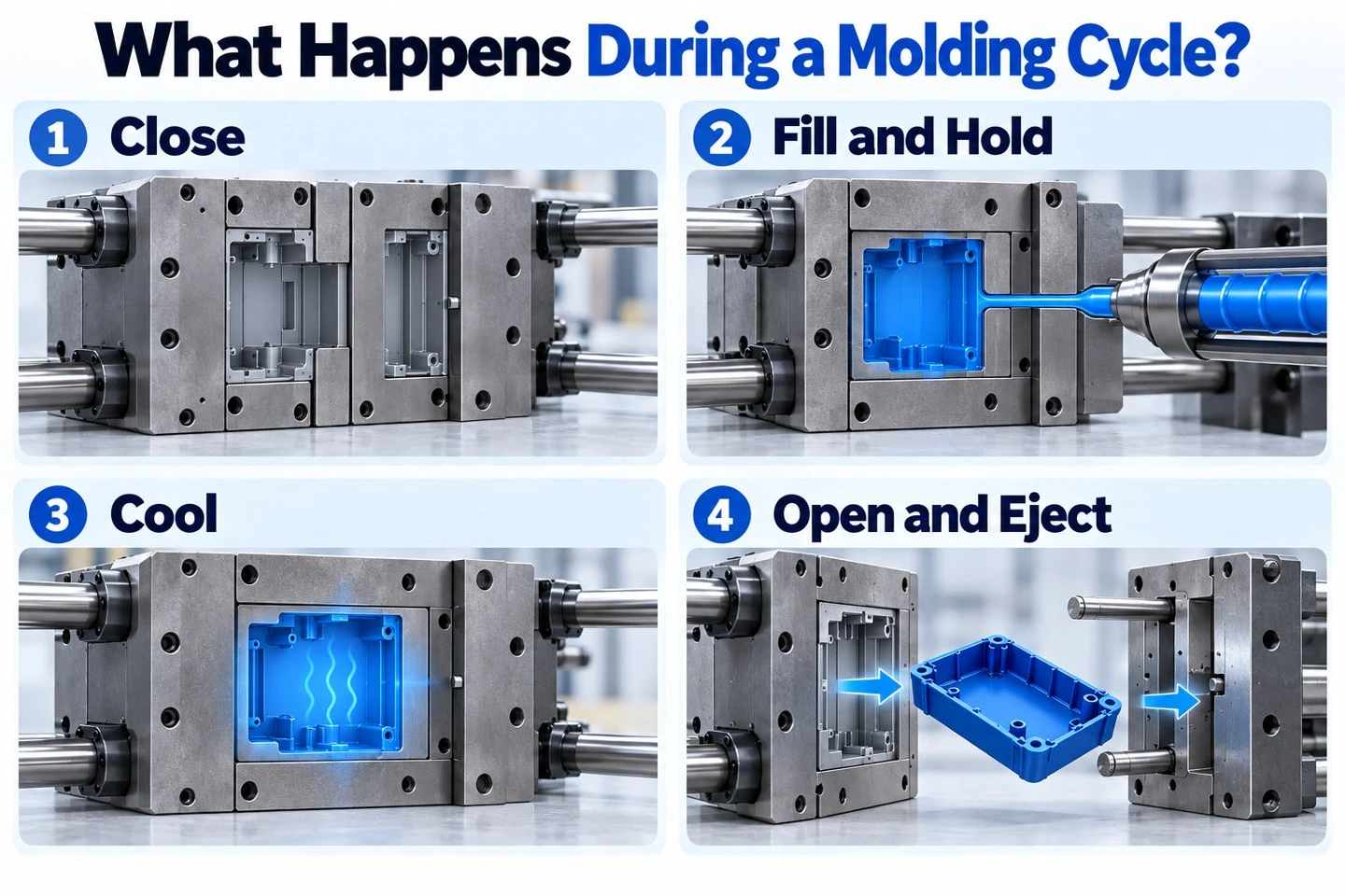
A simplified molding cycle; preparation steps may overlap other stages.
Which marks can appear on the finished plastic part?
Understanding the tool helps explain features found on molded samples. A parting line relates to the division between forming surfaces. A gate vestige relates to material entry and separation. Ejector contact marks relate to release. These process-related marks are different from functional features deliberately designed into the product, such as ribs, bosses, locating tabs and mounting holes.
Define acceptance by location and use. For example, a small mark on the hidden back of an enclosure may be acceptable while the same mark on a sealing land may need a different solution. Agree on cosmetic areas and functional surfaces before tooling. Approved samples and clear drawing notes give both parties a more useful reference than a request for an entirely mark-free component.
How should buyers use this knowledge when reviewing a quotation?
A quotation should connect the product requirements to the proposed manufacturing route. Ask what tooling is included, which design revision was evaluated, what resin is specified and which inspection activities form part of the offer. Where a secondary operation is needed, identify its purpose and whether its cost is included.
For example, a molded industrial housing may need a suitable gate location, controlled lid engagement and protected cosmetic faces. These requirements link tool layout, release and handling to the finished assembly. Our custom injection molded electronic housing page illustrates this type of application; the manufacturing solution must still be evaluated against each customer's design.
What information is needed before tooling approval?
Provide a current 3D model in STP, STEP or IGS format and a dimensioned drawing. Identify the material grade where specified, color, finish, order quantity and intended use. Mark the interfaces that locate, fasten or seal, and explain any operating conditions that influence material selection or testing.
Then confirm that the agreed moldability changes are included in the approved revision and that sample inspection covers the relevant features. You do not need to design the molding machine to buy a custom part successfully. You do need a clear connection between the part specification, the proposed tooling and the evidence used for approval.
The practical answer to "What are the parts of an injection?" is therefore a coordinated system: injection and clamping assemblies, a product-specific mold, controls and appropriate supporting equipment. Their purpose is to produce the required component consistently. Send your drawings, material and quantity requirements to Amanda for a custom plastic injection molding inquiry: Contact: amanda@tjswks.com.