


Contents
- What is a short shot in injection molding?
- How can you distinguish a short shot from other defects?
- Why can molten plastic stop before filling the cavity?
- Why should material supply and shot delivery be checked first?
- How do gates and flow paths influence short-shot risk?
- Why can trapped air contribute to incomplete filling?
- How do wall thickness and small features affect filling?
- Should temperature, injection speed or pressure simply be increased?
- Can a different resin grade solve the problem?
- What does the defect pattern tell you?
- How can trial samples support a useful investigation?
- What information should a defect report include?
- How should you verify that a corrective action worked?
- What should be reviewed before tooling starts?
- What should you send for a custom injection molding inquiry?
A plastic housing arrives with a missing corner. A mounting rib ends before it reaches the surrounding wall. A small clip looks almost complete, but its engagement tip is absent. These defects can be examples of a short shot: the mold cavity has not filled completely, leaving the molded part with missing material. The difference may be obvious on a large edge or difficult to notice on a small internal feature.
For custom industrial plastic parts, a short shot is more than an appearance issue. An incomplete locating feature can change assembly alignment, while a missing wall section can affect protection or sealing. A useful investigation connects the visible defect to the filling process, then confirms that the corrective action works repeatedly. Simply producing one complete-looking sample does not establish stable production.
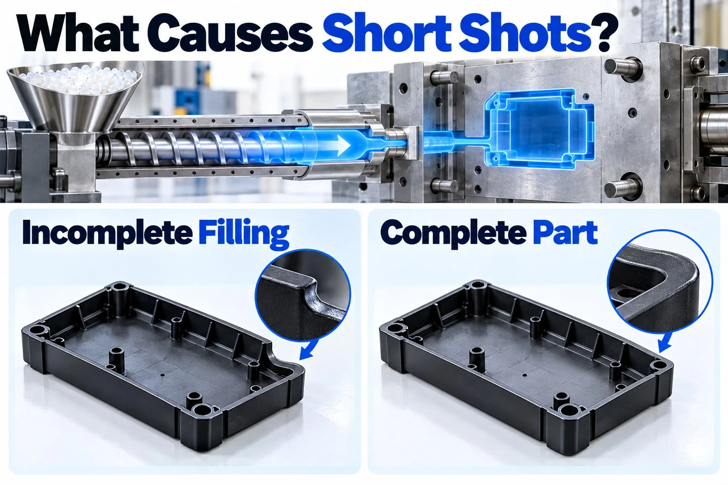
Short shots leave intended geometry incomplete. Illustrative concepts, not production evidence.
What is a short shot in injection molding?
A short shot occurs when injected plastic does not occupy the complete intended cavity. The unfinished region often has an unfilled edge instead of the finished shape defined by the tool. It may appear at a distant corner, a narrow rib, a thin lip or another difficult-to-fill feature. The extent can range from a tiny missing detail to a visibly incomplete component.
Inspection should compare the sample with the approved model and drawing. A deliberately open corner, a designed vent slot and a missing molded feature can look similar in a photograph. Establish which geometry is intended before assigning a defect name. If the item has been trimmed, assembled or transported, also consider whether material was removed or damaged after molding.
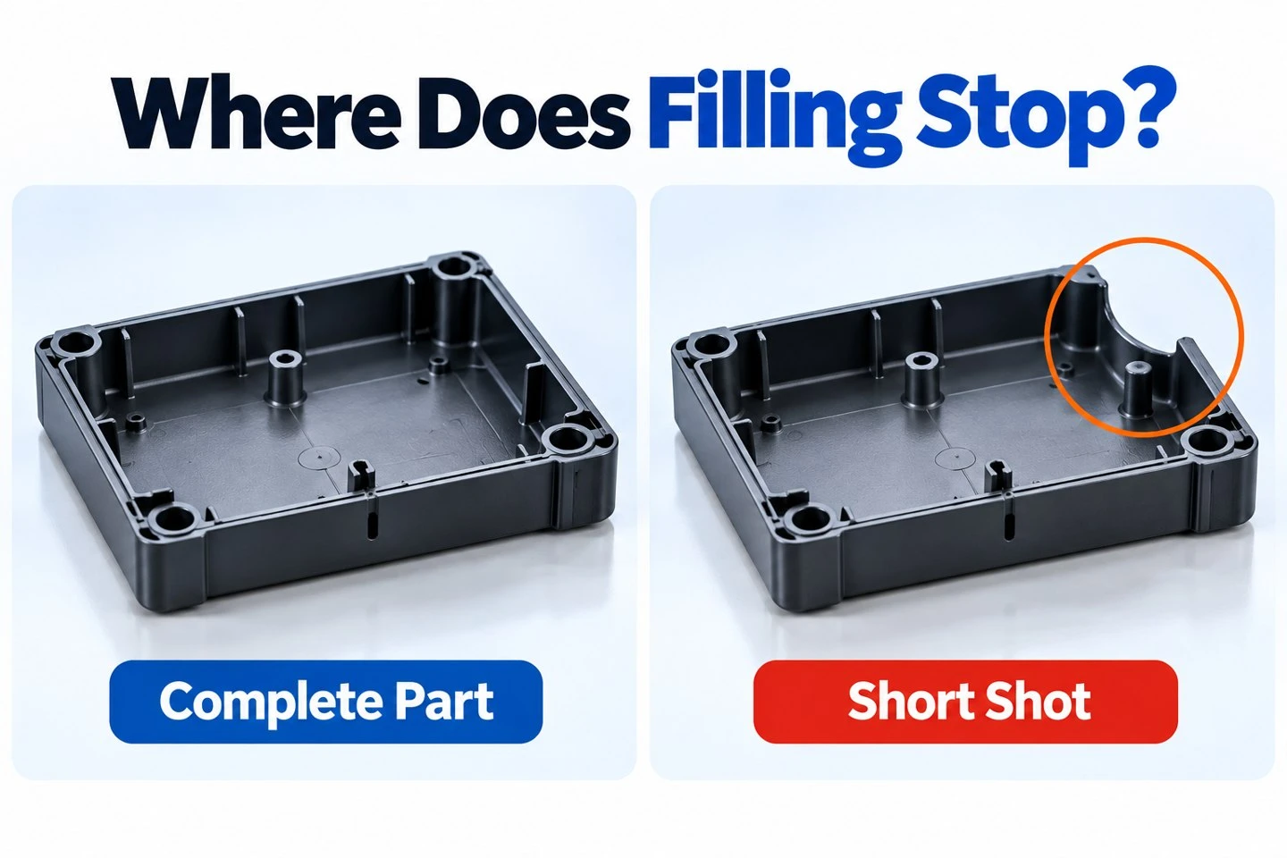
Compare every feature with the approved drawing, including corners and ribs.
How can you distinguish a short shot from other defects?
A short shot describes missing material from incomplete filling. A sink mark is a depression in a surface that has otherwise formed. A weld line is a meeting region between separate flow fronts. A broken clip may have filled correctly and then fractured during ejection or handling. These distinctions matter because each problem leads to different questions about the tool, process and finished part.
Record the defect location, the appearance of the edge and whether it repeats on several samples. If the cavity is complete but the part is distorted, review our article on warpage in injection molded plastic parts. When a visible line is the concern, our guide to injection molding weld lines explains that separate mechanism.
Why can molten plastic stop before filling the cavity?
Material must travel through the feed system and cavity before the flow path becomes too resistant to fill. Thin sections, long routes and restricted gates can make that task more demanding. The melt also loses heat as it contacts the tool. In some geometries, flow reaches a difficult region too late to form the complete feature.
Think of this as a relationship between the available filling conditions and the resistance of the actual geometry. Increasing one machine setting does not automatically remove a restriction, correct an unsuitable flow route or release trapped air. The investigation should identify where filling stops and what is different about that region before choosing a corrective action.
Why should material supply and shot delivery be checked first?
Before discussing a tool modification, verify that the molding cycle receives the intended quantity of material consistently. A supply interruption, feeding problem or unstable delivery can produce incomplete parts even when the geometry previously molded successfully. The technician should review material availability, machine operation and relevant process records rather than assume the drawing is at fault.
From the buyer's perspective, ask whether the defect occurs throughout the batch or only at particular times. Did it begin after a restart, a material change or another interruption? Are several cavities affected together? This chronology can make the technical discussion much more focused. It also helps separate a repeatable design limitation from an intermittent production problem.
How do gates and flow paths influence short-shot risk?
The gate establishes where plastic enters the component. Its position and the route from that point influence which features fill early and which must fill later. A narrow detail positioned after a long flow path may require particular attention. The runner and gate also form part of the delivery system, so evaluating the component alone can miss an important restriction.
Any proposed gate change should be reviewed for its wider effects. Moving a gate can change the visible gate mark, the location where fronts meet and the way the part fills. Adding gates is therefore a design decision, not a universal repair. Review the acceptable cosmetic areas and functional interfaces before approving a change to the tool.
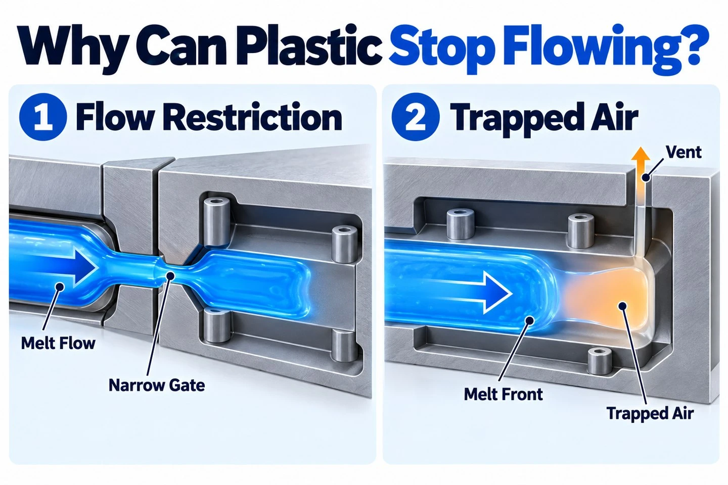
Flow restriction and trapped air require different investigations. Schematic concepts are not to scale.
Why can trapped air contribute to incomplete filling?
Air in the cavity needs a route out as plastic enters. If it becomes trapped ahead of the advancing melt, it can resist further filling. A recurring incomplete feature near the end of the flow path should therefore prompt a venting review as well as a review of the molding settings.
The appropriate vent arrangement depends on the resin, tool and local geometry. A buyer should not request an arbitrary vent depth from a generic checklist. Ask the tool maker to identify the trapped region, explain the proposed escape path and evaluate the change against the risk of flash. Vent maintenance should also be considered if a previously stable tool begins to show a recurring defect.
How do wall thickness and small features affect filling?
Review the path that plastic must follow into the unfinished feature. A thin wall leading into a deep rib, an abrupt transition or a narrow connection can make a local region difficult to complete. The most visible missing area is not always where the underlying restriction begins. Sections through the surrounding geometry can help the engineering team see the full route.
A design revision must preserve the part's purpose. Increasing thickness may affect weight, cooling and the neighboring assembly. Removing a rib may reduce support where it is needed. Before making such changes, identify which surfaces locate, fasten, cover or seal. The best revision balances filling with these requirements and is recorded in the controlled model.
Should temperature, injection speed or pressure simply be increased?
These variables can influence filling, but they should be adjusted within the resin's processing guidance and the equipment's capability. The direction of a useful change depends on the observed problem. A technician needs to know whether the process is limited by delivery, flow resistance, premature freezing or another cause rather than raise every setting together.
A practical trial changes conditions systematically and records the result. Examine the complete component after each meaningful adjustment, including previously acceptable areas. A part that becomes complete but develops flash, discoloration or another unacceptable condition has not yet achieved the required result. The goal is an acceptable and repeatable process, supported by a documented operating window.
Can a different resin grade solve the problem?
Flow behavior varies between resin grades, even within the same broad material family. A grade selected for a demanding mechanical requirement may not fill a particular thin feature in the same way as another grade. That makes the exact material identification important during both the initial design review and defect investigation.
Do not substitute a more easily flowing resin without approval. A material change can also affect dimensions, stiffness, impact response, chemical compatibility or other specified properties. Provide the required grade and identify whether alternatives may be evaluated. If a change is accepted, repeat the relevant sample checks and update the purchasing specification so later batches use the approved material.

Use the observed defect pattern to guide checks of material, tooling and processing.
What does the defect pattern tell you?
A feature that remains incomplete in the same location across repeated samples deserves a focused review of its flow path and local tool conditions. If the missing region varies substantially, investigate process consistency as well. When only one cavity shows the issue, preserve cavity identification throughout the inspection rather than mixing all samples together.
These observations guide the next check; they do not prove a cause on their own. For example, a cavity-specific pattern may justify inspecting its feed or vent arrangement, but the photograph alone cannot establish which change is necessary. Good reporting distinguishes what was observed from what is suspected and what has actually been verified.
How can trial samples support a useful investigation?
The molding team may use controlled filling trials to understand how the cavity fills. Samples from such a trial should be clearly identified and kept separate from approved production samples. Their value lies in showing the development of the filling pattern under known conditions, not simply in providing a collection of incomplete parts.
Ask for an explanation of the observed sequence and the action it supports. If simulation is used, compare its prediction with the actual molded samples and account for differences in material data, tool construction or trial conditions. A colored result image is a discussion aid. Approval still depends on the finished part meeting the agreed requirements.
What information should a defect report include?
Provide the drawing number and revision, material grade, order or batch reference, quantity inspected and quantity affected. Include an overall photograph and a close view with the incomplete area marked. Record cavity identification when available and state whether the issue was present immediately after molding or found later in assembly.
Describe the functional consequence in plain terms. "The clip cannot engage the mating slot" is more useful than "quality is poor." If a missing feature affects fit, provide the mating-part reference or an assembly image. Keep accepted and rejected samples identifiable, so the buyer and manufacturer can compare the same evidence when reviewing the proposed improvement.
How should you verify that a corrective action worked?
First confirm that every required feature is fully formed. Then inspect the other specified dimensions and cosmetic areas. Where the component has an assembly function, test it with representative mating parts. A complete rim, rib or latch is only the start of acceptance; its position and usability must also be correct.
Verification should reflect the source of the problem. An intermittent issue calls for evidence of consistency over an appropriate run, while a cavity-specific issue requires samples from the relevant cavities. Agree on the sampling approach for the application and retain the process and inspection records. A single selected photograph cannot show that a recurring production problem has been controlled.
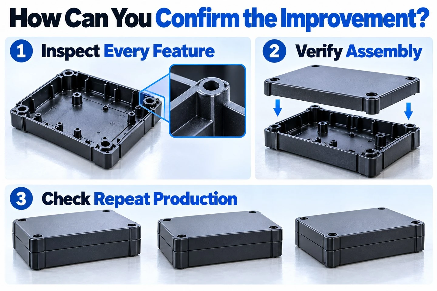
Verify complete features, assembly function and repeatability after corrective action.
What should be reviewed before tooling starts?
Identify thin walls, long flow paths, fine ribs and other features that are difficult to inspect after assembly. Discuss gate location, venting, material selection and critical dimensions during the moldability review. Where the part is complex, ask which risks can be assessed before the tool is manufactured and which must be confirmed during trials.
For an industrial enclosure, for example, prioritize connector access, lid engagement and internal mounting features alongside the external outline. Our custom injection molded electronic housing page provides context for this type of component. The production design remains specific to the customer's drawing and assembly requirements.
What should you send for a custom injection molding inquiry?
Send the current 3D model and dimensioned drawing, preferred material or exact grade, color, surface requirements and expected quantity. Mark any small features that must be complete for assembly or function. If an existing part has a short-shot problem, include clearly identified samples or photographs and explain how the issue affects its use.
Our guide to information needed for a custom injection molding quote can help you organize the enquiry. A clear RFQ lets the manufacturing team discuss filling risks and inspection priorities before tooling decisions become difficult to change.
Short-shot prevention brings together complete filling, an appropriate tool and material, and consistent verification of the finished component. The strongest approval record shows both what was improved and how that improvement was checked against the drawing and assembly. For your next project, send drawings, material and quantity requirements to Amanda: Contact: amanda@tjswks.com.