


Planning a plastic housing or support with metal threads? Send your drawing and assembly requirements to amanda@tjswks.com for a project discussion.
A threaded insert can provide a metal fastening interface in an injection molded plastic part. Selecting the thread size is only the starting point. The insert, surrounding plastic boss, screw and mating component must work together. A specification that describes only "M4 brass insert" leaves important installation and assembly decisions unresolved.
This guide outlines the questions an OEM buyer or engineer should resolve before releasing tooling. Dimensions and acceptance limits should follow the selected insert supplier's recommendations and the requirements of the actual assembly.
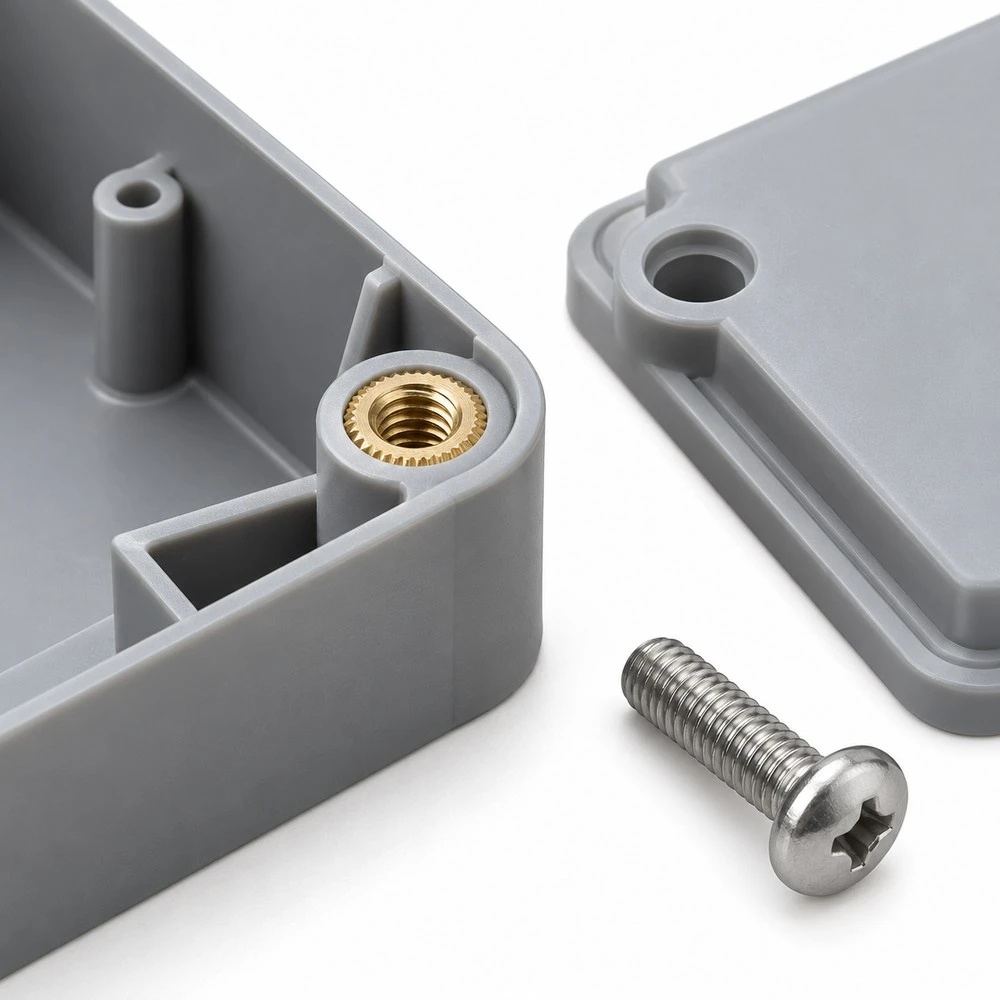
1. Define what the threaded joint must do
Start with the assembly rather than the insert catalogue. Is the cover removed for service? Does the screw locate a component, maintain a seal or retain a bracket? Will the joint experience repeated opening, vibration, temperature changes or contact with cleaning chemicals? Record the relevant conditions without assuming that one insert design suits every application.
Identify the exact resin grade, filler content and expected molding condition. A material name such as nylon or ABS is not a complete engineering specification. The insert supplier needs enough information to recommend a compatible insert and installation route. For a broader component discussion, see our custom plastic parts and nylon parts categories.
2. Select the installation route before finalizing the boss
Heat installation, ultrasonic installation, molding around an insert and mechanical installation require different planning. They should not be treated as interchangeable operations using a common hole drawing.
| Installation route | Questions to resolve |
|---|---|
| Heat or ultrasonic installation | Is the thermoplastic suitable for local remelting? Which insert geometry, hole dimensions and controlled installation process are specified? |
| Molded-in insert | How is the insert located and retained in the tool? How are the internal threads protected, and how is insert position checked? |
| Press-in or self-tapping insert | Is the insert intended for this method and resin? What surrounding material and installation controls are needed to manage expansion or cutting forces? |
Heat and ultrasonic installation rely on thermoplastic material flowing around the insert's external retention features. Thermoset materials do not remelt in the same way. Confirm the process with the insert manufacturer instead of choosing a method solely because equipment is available.
3. Specify the complete hole and boss geometry
The insert's outside diameter is not a substitute for a hole specification. Request the recommended hole diameter or profile, depth, permitted draft and installation position for the exact insert model. Define which dimensions apply to the molded hole and which describe the completed assembly.
Provide enough space around and below the insert
Review the boss outside diameter, surrounding wall, nearby edges and ribs together. A narrow boss may be vulnerable during installation; adding excessive material can create molding difficulties. The solution should balance installation requirements with the molded part's wall layout. Avoid copying a boss from an unrelated component without reviewing its material and load path.
For a blind hole, allow the space required by the selected installation process and the intended screw. Check the drawing section through the entire joint. Hole depth, insert length and screw penetration are related dimensions, but they are not the same measurement.
Make position and alignment inspectable
Identify the reference surface for insert height and the datum for its axis. If a mating plate must sit flat, show how that plate contacts the boss and insert. Agree whether flushness, protrusion or recess is acceptable. A general note such as "install correctly" does not tell an inspector what to measure.
4. Check the screw and mating component together
Choose screw length from the assembled stack, including washers, cover thickness and any compression of the joint. Ensure the intended thread engagement without allowing the screw tip to bottom out. A screw can reach an apparent tightening condition while failing to clamp the mating component as intended.
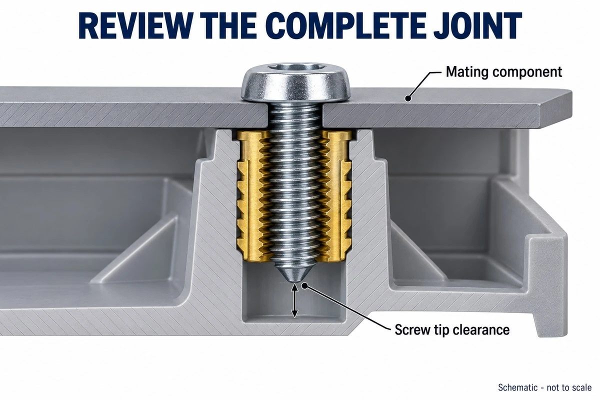
Review the mating hole clearance and bearing surfaces using the insert supplier's joint guidance. Define the screw specification and assembly procedure as part of the drawing package. Do not assign a universal tightening torque from thread size alone: the complete joint, insert retention and plastic structure all affect the acceptable assembly window.
5. Agree on sample acceptance before ordering
Turn the intended function into a written sample review plan. The following are questions to agree with the project team, rather than claims that a supplier has already performed these checks:
- Which molded dimensions and insert positions must be reported?
- What constitutes unacceptable cracking, deformation or thread contamination?
- Which screw, mating component and tightening procedure will be used for assembly review?
- Are torque-out, pull-out or repeated assembly evaluations required, and who defines the method and acceptance limits?
- Do temperature, moisture conditioning or chemical exposure need to be represented?
Use representative parts and the agreed installation process when evaluating samples. Record the resin grade, insert identification and relevant assembly conditions so that results can be interpreted. A successful hand-assembled sample does not by itself establish an approved production process.
What should an RFQ include?
Provide the part drawing and 3D model, exact resin requirement, insert part number or functional brief, thread specification, installation route, mating component details, screw dimensions and required inspection criteria. Include the expected order quantity and identify any dimensions still open for review.
If the insert has not yet been selected, mark it as an item requiring engineering agreement. Keeping that uncertainty visible is more useful than placing an unverified insert model on the tooling drawing.
For an injection molded plastic component enquiry, email amanda@tjswks.com with your drawing, material and fastening requirements. We can discuss the project scope and the information needed for quotation.